Over the next month we’ll be doing some work to consolidate our NTP stratum 2 and 3 services into what will hopefully (subject to antenna installation) be a four system stratum 1 service. All historical IP addresses and DNS names will continue to function but keen IT officers in local units monitoring the central service may spot individual NTP nodes disappearing and reappearing one at a time as the transition takes place.
The intended audience of this post is IT Support Staff inside the university (the university has a federated support model) however it is public in the hope that it’s of interest to other sources.
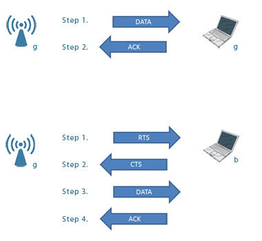
If you aren’t sure what NTP is, it provides a method of network time synchronisation between computers. This is important for log correlation for troubleshooting and security analysis, but it’s also essential that the time be within a given synchronisation threshold in order for some types of encrypted communications and authentication to take place. The traditional method was to have a few servers in your organisation querying external accurate sources, a tier of servers (stratum) below this then queries those servers and all your hordes of client machines queried that lower tier.
Why?
You might perceive NTP services as fairly maintenance free. This is true, but the main reason for the work is to separate out the NTP service from other services – currently each NTP node is served by a machine that’s also supplying another more critical service. The main mail relay nodes provide the current stratum 2 and various assorted servers provide stratum 3 (a database server, a webserver and so on).
Normally this isn’t a problem, but it can cause issues/complications when there’s work to be done on one service/host because it affects the operation of other service that’s also resident. Some of these services/hosts need replacing or other maintenance work, and separating out NTP is a fairly small task that makes that maintenance easier.
The full set of objectives is
- To consolidate stratum 2 and 3 services (make the service simpler to understand)
- To move the public NTP service to hosts dedicated to only that role
- To add non network time sources (GPS and Radio)
- Improve the user facing documentation
- To ensure the service is geographically spread out
On this last point it’s worth noting that we always try to spread services out, however in this case we made an error. We very carefully/methodically audited and spent time moving our main mail relay nodes to different physical sites one at a time so as to make the mail relay service fault tolerant of an issue at any single physical site. The mail relay had a lot of nodes at the time and as part of this work four of the mail nodes (that in hindsight happened to be the four that jointly host all the NTP stratum 2 service interfaces) ended up at one remote site, a situation which Murphy spotted and took advantage of with a power cut locally at the site. In the aftermath we received a number of very polite suggestions that we should try and spread our NTP service out geographically so as to avoid single points of failure based on physical location which we had to politely acknowledge was indeed true.
The Solution
We already had an NTP appliance, which due to human resource constraints (NTP is not a politically squeaky wheel) hadn’t been deployed into a production role. Some testing on this revealed it could at least run as a normal network synchronised stratum 2 device, with successful GPS and radio antenna installations able to set it running as a stratum 1 source. It could listen on multiple interfaces, could have custom NTP configuration added and could also be secured for network duties on a public IP address.
The plan was hence to purchase three more of these, making four appliances in total. The historical NTP stratum 2 and 3 service IP addresses currently in use by many devices university wide would be served by the appliances (one address from each stratum by each), and each appliance would be placed at a different physical location. The user documentation would be updated and with approval of the owners of various buildings we should be able to install antennas to elevate the service to Stratum 1 on all four appliances.
So this solution would separate the NTP service out onto dedicated hardware and so the NTP service would not be affected by alterations or work on other services (within reason: a loss of the backbone network obviously wouldn’t be survivable without service connectivity disruption for instance).
It’s unlikely that we’ll lose the internet connectivity to the joint academic network for any length of time but just in case, the stratum 1 independent time sources would prevent the time service drifting or shutting down which in turn will prevent time related issues with kerberos authentication and similar in a suitably apocalyptic disaster scenario. The GPS/radio antennas are also fairly cheap and shouldn’t need replacing.
The Cost
The total cost of all three extra appliances including GPS/radio antennas and a 5 year hardware warranty was less than the cost of a single typical mail node.
We spent a little more money on one of the appliances (in the region of £100 more) to make it a more powerful model, with the idea that once our service deployment is complete we’d like to offer this node as a time source back to the UK NTP pool. I think this is ethical behaviour, to contribute back to the community.
The human resource time including physical deployment, antenna mounting, documentation and so forth is perhaps in the region of 4 -5 person days – the majority of which will be the political and physical work involved in having holes drilled in buildings for antennas to be installed. Configuration and testing is only two days including initial setup, this blob post, updating user facing documentation and IPv6 testing.
What’s the status?
The status of this is that the hardware has arrived, has been labelled and base configured and is working on live IPv4 testing addresses. I’m performing the IPv6 testing today and preparing revised service documentation (essentially better instructions on service usage). One of the four sites has an antenna installation request open, I’ll be creating requests for the other three sites today.
We should be able to start moving stratum 3 nodes to the new service today, but this will be done one at a time, verifying the service after each move.
Stratum 2 is more complicated, due to the fact the actual historical IPv4 service address is also in use by another internal service. I need to work on that related service to separate the addresses (which actually means migrating the other service to a new host) which may take a 4 weeks not by itself, but perhaps using each weeks at risk period to move one node at a time.
General queries people might have
- “I think your time is probably of low quality, I think it’s 5 minutes out! I’m going to use the UK NTP pool instead!”
Some years ago, access to our stratum 2 nodes was by registration only (but stratum 3 was unrestricted), so people that didn’t notice this restriction would sometimes point their servers at stratum 2, watch the time drift out on their server and then complain that our service must have an incorrect time (out by the amount that their device had drifted out by) and that they’d have to use an external source instead (which then worked and corrected their time because the external source replied to them, the symptoms reinforcing their belief that our time was minutes out). We removed the restrictions since NTP load was not an issue to the modern servers and since it was causing unnecessary user confusion and wasted effort.
The above is an example of why it’s important to drill down to testable evidence wherever possible, rather than guesses based on symptoms, so if you’re unfamiliar with NTP and want to see what the exact accuracy of our service is, log in to a Linux machine and use ntpq -p
ntpq -p ntp1.oucs.ox.ac.uk
 remote refid st t when poll reach delay offset jitter
==============================================================================
+badajoz.oucs.ox 193.62.22.82 2 u 408 1024 377 0.357 -0.918 0.132
*corunna.oucs.ox 193.62.22.74 2 u 551 1024 377 0.317 -1.496 0.413
+vimiera.oucs.ox 131.188.3.221 2 u 395 1024 377 1.250 -1.482 0.221
-salamanca.oucs. 131.188.3.222 2 u 888 1024 377 0.887 -0.760 0.546
-2001:630:306:10 158.43.192.66 2 u 544 1024 377 8.685 -0.061 0.184
-ntp0.cis.strath 192.93.2.20 2 u 601 1024 377 10.182 0.806 0.058
 LOCAL(0) .LOCL. 13 l 12 64 377 0.000 0.000 0.001
Some of the formatting will appear better on the terminal but essentially you can see exactly what a node is synchronised with. Note that offset and jitter is in milliseconds. There’s probably similar commands for Windows and Mac which I leave as an exercise for the reader to find. It’s fair to say that the NTP results are of good quality.
So feel free to use the UK public NTP pool if you wish, but please use repeatable tests, not guesses when making technical decisions.
- That command doesn’t work outside the university, it just times out. I can query the time however with ntpdate or ntpd however.
Sources inside the university can query the full state of our NTP servers, sources externally can just retrieve the time.
NTP uses UDP, which is a connectionless network protocol which in layperson terms has the side effect that it’s easier to forge the sender IP address. There’s been some fears that NTP servers can be used as an amplification attack vector, essentially someone says “Hi I’m www.example.com, tell me all about your current status” our NTP server then replies with a lot of information, but the destination we are sending to was not actually the originator. The attacker would send such a request to many NTP sites at once with the aim being to make the forged sender receive massive amounts of traffic that would make their normal business operations unable to function.
By restricting status queries we reduce the potential usefulness of our service for malicious use, whilst still serving the core server (time readings). It is regrettable not to be able to offer the server status externally but we may have a better solution in the longer term.
- Can I use the NTP service outside the university?
If you’ve a laptop set to use one of our NTP servers it will be able to retrieve time from our service inside the university or out. If your device only accepts one name/address you could use the round robin DNS record specifically ntp.ox.ac.uk or ntp.oucs.ox.ac.uk but the user facing documentation will be updated shortly with more details and ntp.conf examples of Linux system administrators and similar.
If you are not a member of the university the short version is that non university sources should use the UK NTP pool. In reality if you point your home desktop at our NTP service we wouldn’t notice but in terms of configuration it’s better for you to use the UK ntp pool , which we hope to contribute to once the setup is finished. So use the name of uk.pool.ntp.org in your configuration if you are an external non university member in the UK.
On this subject commercial entities are another matter that can cause issues and we’ll be updating the official documentation with some suitable legal disclaimer. Note that with regards to the ntp.org pool vendors get specific instructions on what to do.
- What if one node suffers some sort of issue and the time drifts out?
If you define multiple nodes in your configuration, your ntp server/client will automatically mark as bad any server that drifts out significantly compared to your other time sources and will ignore it.
- Further questions
If you are a member of university IT support, do please email in to networks at the usual address with any concerns, corrections or queries. External persons might prefer to reply on this blog post.