This is a continuation of the series of blog posts describing the Linux servers in the middle of the new eduroam infrastructure.
Packets sent by your eduroam client eventually end up on one of the Linux boxes in the eduroam infrastructure. How this is achieved could be described as “necessarily complex” due to the decentralized nature of Oxford IT provisioning and it will not be covered here (for those interested, we employ a mechanism called MPLS.) This post will describe the relatively simple task of how traffic comes in on one interface and goes out another in a Linux box. But first, some background information on some terminology.
Inter device communication and TCP/IP
You may safely skip this section if you understand TCP/IP at any significant level. Before I joined the networks team I was a web developer for a department within Oxford University. In a sense I am writing this section to someone like my former self, with enough knowledge to set up a LAMP stack and plug it in, but not much more! It’s not a complete picture and some parts verge on being totally inaccurate for the sake of simplicity, but it will suffice for the purposes of this post and for boring people at dinner parties.
Ultimately, communication between two devices, be they computers, phones or tablets involves transferring information from point X to point Z. Each device network interface has a (theoretically unique) number assigned to it called a MAC address. For X talking to Z, one form of communication could have each packet addressed to the MAC address of Z and send it out the interface (these “packets” are called frames when they’re addressed by MAC address). Now if X and Z are connected by a wire, that’s fine. Even if the two devices are connected via a few intermediary devices this form of communication works. The intermediary devices would have multiple cables, with each device knowing which cable to send a frame down because it would store MAC address to cable mappings in a table (called a CAM table.) The CAM tables can be populated by several processes, of which one is listening to Address Resolution Protocol, or ARP responses. ARP is essentially shouting out “Where are you Z?” and waiting for the reply “I’m here, my MAC address is 00:11:33:55:22:ff” . This works quite well for a few devices. However, the whole process cannot scale to the size of the internet as each intermediary device would need each MAC address that’s in use stored in memory. The ARP queries would also clog up the network quite badly. There are other reasons why this cannot scale, but I will not go into those here.
This is where IP comes in. As well as a MAC address, each network interface is given one (or more) IP address. IPs can be grouped into networks so a device does not need to know every MAC address in a network, just the right direction to send packets for that network. When X wishes to communicate with Z via IP, it asks itself the question “Is Z on my network?” If it decides yes it is (I’ll say how it does that in a minute), using ARP it finds the MAC address of Z, wraps the information to send in a packet addressed to the IP of Z, then wraps that packet in a frame and sends it. This is called communication at layer 2.
If however it says to itself “no, Z is not on my network”, then it calls out for the MAC address of a gateway “OK, who has address 192.168.0.254?” to which a gateway device will reply “that’s me! I have MAC 00:11:33:55:ee:ff.’ The gateway IP address is defined at initial network configuration and is typically provided by DHCP, but you may put any IP address on your network there (whether the host at that IP address knows what to do with the packet is another problem.) The packet will then go, from gateway to gateway using multiple frames along a route towards Z before finally arriving at its destination. This is traditionally called communication at layer 3.
It would be prudent to point out that the packets wrapped in frames for inter and intra network communication look similar. The only distinction is that intra network communication has the MAC and IP address such that they are for the same device. For inter network communication, the IP is for your ultimate destination, the MAC address is for the gateway of the current network which will get the packet closer to that destination.
How did it know whether a host is on its network? The following is a really hand-waving sidestep to an answer. I suspect most people reading this already know this, but for the benefit of the few that don’t, I should give a brief explanation. IP addresses can have their network information appended to the IP address using something called CIDR notation. It looks something like 192.168.0.15/24. The number after the slash is the size of the network. The smaller the number is, the larger the network. Some key numbers for the size of network:
- /24 -> Last octet (the number after the last dot) can be anything from 0 to 255.
- /16 -> Last two octets can contain any number from 0 to 255.
- /8 -> Last three octets can contain any number from 0 to 255
- /30 -> A linknet with a network of 4 contiguous addresses, of which two are usable as host addresses (the middle two). The first address is a multiple of 4, so it’s any 4 contiguous addresses including the IP address given, with the first address being a multiple of 4.
Some examples
- 10.10.10.10/24 -> The address 10.10.10.10 is on the network which encompasses 10.10.10.0 to 10.10.10.255
- 10.25.25.30/30 -> The address 10.25.25.30 is on the network which encompasses 10.25.25.28 to 10.25.25.31
- 10.25.25.29/30 -> Same network as above
There are other ways of representing these networks, like 10.10.10.10 with netmask 255.255.255.0. I will only be using CIDR notation for this blog post however. I should also say that no knowledge of TCP is needed for this discussion on routing.
An aside on the OSI model
When I say that intra network communication (ie. by MAC address) is “at layer 2” and inter network communication (ie. by IP address) is “at layer 3” I am referring to the layers as defined in the OSI model. This is a theoretical framework to separate duties that are used for effective communication between two devices. The plan was for OSI to have 7 layers, with a protocol at each layer (eg. one for encryption, one for session management) where swapping any protocol at any particular layer did not affect the other layers. That was the plan anyway. In reality the TCP/IP model gained traction before the OSI model crystallized and the rest is history. It’s just the numbering convention that has stuck even though it bears little resemblance with the internet we use today. For those interested there is a fantastic article on the subject.
In summary
A packet, addressed by IP wrapped up in a frame, addressed by MAC address
So, in bullet point form, the facts needed for the rest of the blog post are:
- Communication between two devices on the same network is at “layer 2”, addressed by MAC address using frames.
- Communication between two devices on different networks is at “layer 3”, addressed by IP using packets.
- Layer 3 packets are wrapped in layer 2 frames
- For intra network communication, the IP of the packet and the MAC of the enclosing frame are for the same device
- For inter network communication, the IP remains static for the entire route (ignoring NAT), but the MAC address changes for the next gateway device as it traverses networks.
- ARP is the process to map IP addresses to MAC addresses
- Knowledge of TCP is not needed for understanding this blog post.
Routing tables on Linux, what do they do?
If you fire up a Linux client, connect it to eduroam and run “ip route” at the terminal, you will see something similar to what I have:
default via 10.30.255.254 dev wlan0 proto static
10.30.248.0/21 dev wlan0 proto kernel scope link src 10.30.248.31 metric 2
This is about as simple a routing table as you could possibly get. It’s saying that everything not destined for the same host “localhost” (<alert type=”spoiler”>these routes are defined in another table </alert>) has two choices.
- If it’s for a host on the network 10.30.248.0/21, then send it out the wlan0 interface with a source address of 10.30.248.31. This is layer 2 as no gateway is defined.
- If it’s not for a host on this network, then send it out the wlan0 interface destined for the gateway 10.30.255.254. The gateway should know what to do with it. This is layer 3.
The Cisco wireless LAN controllers do something called client isolation so that anything for the network 10.30.248.0/21 except the gateway gets blocked, so in reality we only make use of the default rule (the other rule is used to find the gateway’s MAC address). Client isolation may not necessarily be true for some college and departmental deployments of eduroam, but the end result is the same; most traffic ends up at the gateway 10.30.255.254 and by complicated routing practices, it ends up on the NAT box to be routed to the outside world.
Let’s look at a possible routing table on the eduroam NAT boxes, with IP addresses changed slightly to protect the innocent and some additional routes removed:
- bond0 is the internal interface, facing the eduroam internal network. This has address 192.168.34.97
- bond1 is the external interface, facing the outside world. This has address 192.168.120.5
- eth0 is the management interface, facing the server room network, which has a gateway to the outside world as well. This has address 10.2.2.2. This is used for backups, logging, monitoring and SSH access.
Here is a pictorial representation of this:
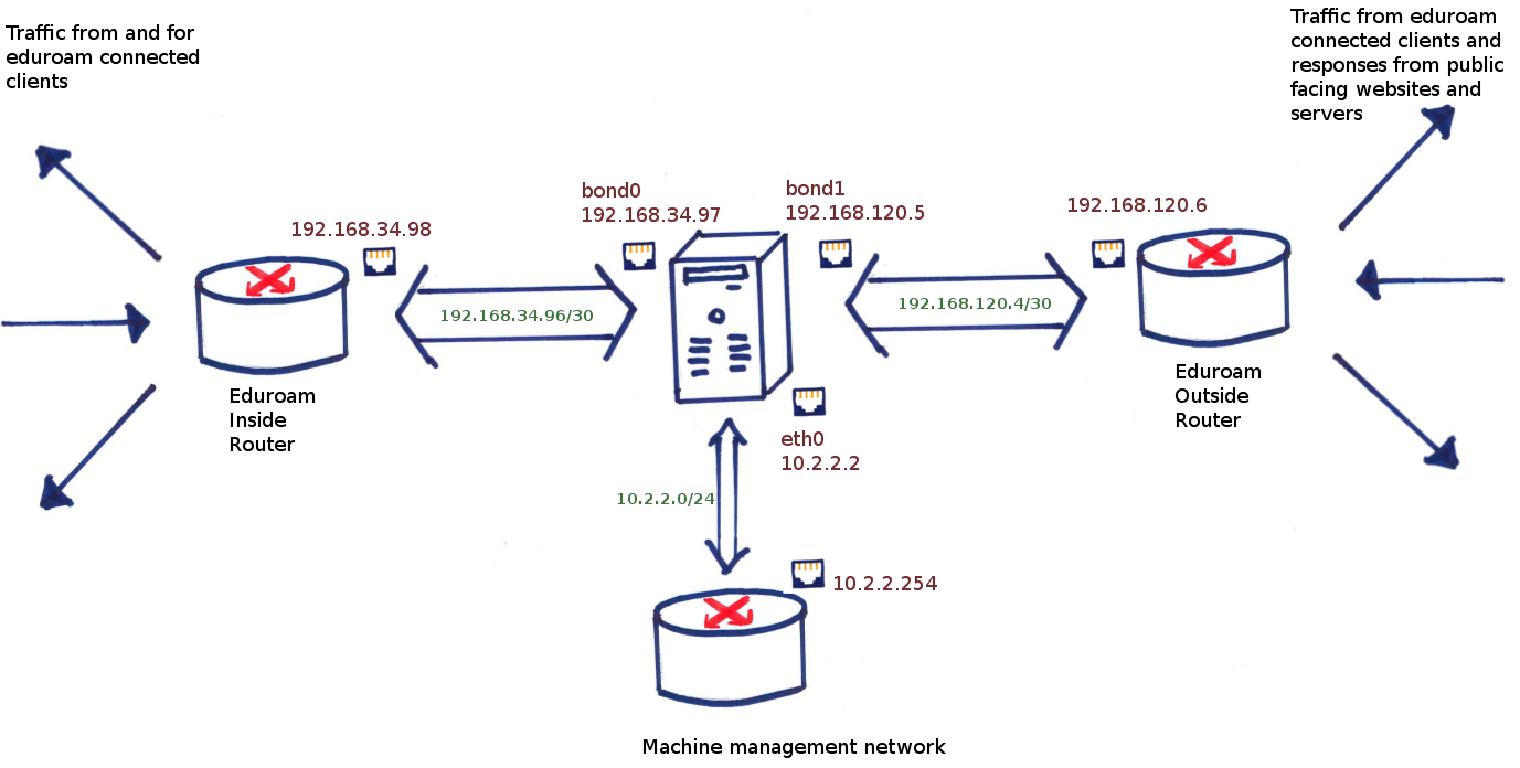
A representation of what the NAT box routing looks like
# ip route list
default via 192.168.120.6 dev bond1
10.16.0.0/12 via 192.168.34.98 dev bond0
10.2.2.0/24 dev eth0  proto kernel  scope link  src 10.2.2.2
192.168.120.4/30 dev bond1  proto kernel  scope link  src 192.168.120.5
192.168.34.96/30 dev bond0  proto kernel  scope link  src 192.168.34.97
Let’s clean this up by removing the proto and scope definitions:
default via 192.168.120.6 dev bond1
10.16.0.0/12 via 192.168.34.98 dev bond0
10.2.2.0/24 dev eth0  src 10.2.2.2
192.168.120.4/30 dev bond1  src 192.168.120.5
192.168.34.96/30 dev bond0  src 192.168.34.97
A packet is checked against the list from bottom to top, and the first rule that matches is the one used. The top rule, the one labelled “default”, is the catch-all and defines that we send everything out the bond1 interface via the gateway 192.168.120.6, and which eventually ends up on the janet router and then the outside world. When a reply comes in, the routing tables are consulted (after the NAT has already changed the destination to my private address 10.30.248.31) and it goes out the bond0 interface because of the second line in the list above. The “via 192.168.34.98” means that it is a route not on the current network so needs to go via the gateway 192.168.34.98. Eventually the return packet will end up at an eduroam client.
If you look again, you’ll see two networks 192.168.120.4/30 and 192.168.34.96/30. These are linknets that we use for incoming and outgoing traffic (the former is between the server and janet, the latter is between the server and the eduroam clients.) We have seen its use above in defining a gateway for the inside traffic (10.16.0.0/12) and they are the smallest possible multi-host networks that you can define (i.e. a network comprising 2 hosts). Each side of the link defines the other as the gateway for a particular subnet.
Why do I need to define linknets?
Let’s change the ip routes via the ip command to remove the use of a gateway.
# ip route change 10.16.0.0/12 dev bond0

# ip route list
default via 192.168.120.6 dev bond1
10.16.0.0/12 dev bond0
10.2.2.0/24 dev eth0  src 10.2.2.2
192.168.120.4/30 dev bond1  src 192.168.120.5
192.168.34.96/30 dev bond0  src 192.168.34.97
Will this work? Well, that depends on how the other end is configured. If it is set up for proxying arp requests, the Linux box will send an ARP request to obtain the MAC address for a client, say 10.16.1.1 and the router at the other end will respond with its own MAC address, thinking along the lines of “what I’m sending is not correct, but if you send it to me anyway, I’ll deal with it so it doesn’t matter.” The frames containing the packets will be addressed to that MAC address, and the other end will recieve them happily.. If it’s not configured like that, then the router will not respond, because it doesn’t know what the MAC address for that IP is, the Linux box will not know where to send the packet and it ultimately gets dropped.
Let’s revisit what happens when arp proxying is turned on (which appears to be the default on Cisco 4500-X devices.) Now the box will work as intended, but for each and every address, the box does an ARP lookup and stores the result in its MAC table. For low levels of traffic this is fine, but once we get to 30,000 devices simultaneously connected (as we do sometimes on eduroam), this is a problem. The MAC table will be full, all with the same MAC address, that of the router at the other end of the cable.
How do I know this? Well regrettably I made a configuration error that escaped into the early deployments of the new eduroam. There is another way to fill the MAC table, and that is to configure the gateway as the address on the box itself, rather than the router’s address (in our example, the via would be 192.168.120.5). In this case we’ve effectively said that the next hop of the frame is localhost. The Linux kernel makes the best of a bad situation and treats this as communication at layer 2. In the early stages, everything looked good and traffic was flowing reasonably. However, as the number of connected clients grew, the problem manifested itself with sluggish response as the CAM table became full and had to be garbage collected.
You can see for yourself the MAC addresses for systems on your network with a simple command
$ ip neigh
I would have expected a list of 10 or at a pinch 20 entries. When I ran it on the server, it responded with a list of 1024 addresses, the default maximum.
The fix was relatively easy, just changing the next hop to the correct address fixed everything, but diagnosing the problem (i.e. getting to the point of knowing to run ip neigh)was a little harder. This is an example of what I saw in the kernel message buffer
[1026987.757575] net_ratelimit: 1875 callbacks suppressed
with no supplementary lines to hint at what those callbacks were. Online research suggested to me that this was a syslogging problem (i.e. syslog was generating too many log lines) which led me down the wrong path (the syslogging for this host is indeed intentionally very verbose). Fortunately, and I am gratefully indebted to him for his help, my friend Robert Bradley found an incident report describing the exact same symptoms. According to that report, it seems that the 3.10 kernel suppresses the important error message “Neighbour table overflow” (we use Debian Wheezy with a backported kernel for reasons to be expanded upon in a future blog post.)
Hello, syslog, are you there?
Let’s go back to the routing table shown above. There’s an elephant sized problem that hasn’t been addressed, involving an asymmetry in the routing. Our syslog messages are not reaching our central logging server.
If we look more closely at the routes above, you may spot the problem: our syslog server is on the machine room network (eth0) but the default route is out bond1. I should emphasize this has nothing to do with what interface the syslog daemon is listening on. It is perfectly entitled to listen on eth0 but reply on bond1, and in fact if it’s doing things according to the OSI model, it should not even know what interface it’s replying to because all it cares about is its application layer before handing the packet to the OS to deal with the lower layers.
We would like it to send traffic out eth0. We could patch the problem, by pushing traffic for the university out eth0, for example:
$ ip route add 129.67.0.0/16 via 10.2.2.254 dev eth0
But that’s no good either. What we’ve just done is push all traffic for the university out the eth0 interface. This is bad because people on eduroam should be connecting to university services as if they are external to the university (eth0 is on the university network) and, more practically, the eth0 has limited bandwidth because it’s just meant for server management. Fiddling with the address ranges in the above route only serves to mask an underlying design flaw.
VRF to the rescue
Virtual Routing and Forwarding (VRF) is where you have multiple routing tables, and which routing table you use is chosen based on properties of the packet to be routed. It could be the interface on which the packet came in on, the source address of the packet or some other criterion as we’ll discover later.
Looking at the diagram above we can construct a high level overview of what we want:
- Packets coming in for forwarding on bond0 can only leave on bond1
- Packets coming in on eth0 should never be forwarded
- Packets coming in for forwarding on bond1 should only leave bond0
- Packets generated by the host should only leave eth0
Rule 2 is easily sorted by iptables or sysctl, there is no need to add VRF to this. Rule 3 should already be sorted because once the replies have been translated to the private address range 10.16.0.0/12, there is already a rule to send that out bond0, and again anything else can be dropped. It is rules 1 and 4 that we need the second routing table for. In an ideal world, the default gateway should be out eth0 unless forwarding an eduroam packet, when its default gateway should be bond1.
Again, fire up your linux client and look at the file /etc/iproute2/rt_tables
$ cat /etc/iproute2/rt_tables
#
# reserved values
#
255     local
254     main
253     default
0       unspec
These are the names of routing tables, and it looks like there are some already. For reasons that I don’t understand, the default table is not the default one, and is in fact empty:
$ ip route list table default
$
The local one is set up by the kernel. You can look but don’t touch!
It’s the main one that has the routing table we know and love:
$ ip route list table main
default via 192.168.120.6 dev bond1
10.16.0.0/12 via 192.168.34.98 dev bond0
10.2.2.0/24 dev eth0  src 10.2.2.2
192.168.120.4/30 dev bond1  src 192.168.120.5
192.168.34.96/30 dev bond0  src 192.168.34.97
The numbers next to the routing tables have to be unique for each table and have to be in the range 0 to 255 (because 256 VRFs ought to be enough for anybody.)
Let’s create one by appending to the rt_tables file
# echo 200 Eduroam-egress >> /etc/iproute2/rt_tables
and create a rule so that any packet coming in on bond0 for forwarding always uses this routing table
# ip rule add iif bond0 table Eduroam-egress
and finally, create only one route in that table, the default gateway
# ip route add default via 192.168.120.6 dev bond1 table Eduroam-egress
We can now change our “main” default route to go via eth0, so that SSH behaves as we would expect.
How does this work with our NAT setup? As described in a previous post, our rules are done in POSTROUTING, so the fate of the packet has been sealed by this point. Anything done by the NAT rules is done after the routing tables have been consulted. Implicit in this is that return traffic is translated back into its private address before routing table consultation, so that works as you would hope as well.
The rules created by ip command will only last as long as the system is up. Any reboots will flush any config (a boon if you’re testing your routing and have accidentally locked yourself out of your own SSH session, but not so great otherwise) so in our case we created scripts to persist our changes. You can define the routes using the /etc/network/interfaces command, but in our case, with daemons to start and stop with the interfaces, we found it easier to create a bash script bond0-if-up and have in our /etc/network/interfaces
auto bond0
iface bond0 inet static
        bond-slaves eth6 eth4
        address  192.168.120.5
        netmask  255.255.255.252
        bond-mode 802.3ad
        bond-miimon 100
        bond-downdelay 200
        bond-updelay 200
        bond-lacp-rate 1
        bond-xmit-hash-policy layer2+3
        txqueuelen 10000
        up   /etc/network/eduroam-interface-scripts/bond0-if-up
        down /etc/network/eduroam-interface-scripts/bond0-if-down
If we were using Debian Jessie (which is currently unreleased), its default init system systemd would be able to do this using much simpler dependency rules, but for the moment, these scripts running on interface up and down should suffice.
How configurable is Linux’s rt_tables?.
Asked another way, how fine-grained can you define which routing table to use? We are deciding the routing table based on the interface the packet for forwarding came in on. Can we go deeper? Well, this being Linux, it’s almost certainly more configurable than you need it to be. (As in the previous post’s section on ipset, the following is nothing I have tried myself. It may work as advertized. I wouldn’t advise doing this in anything other than a toy environment.)
A not often mentioned feature of iptables is the ability to mark a packet (tagging would be a more recognizable term for it.) Most systems administrators are familiar with ‘-j ACCEPT’, or ‘-j REJECT’, but there are more options (we have already seen ‘-j SNAT’.) One of these options is ‘-j MARK’. The following is an example
iptables -t mangle -A PREROUTING -s 10.16.0.0/12 -p tcp \
	-j MARK --set-mark 0x8
iptables -t mangle -A PREROUTING -s 10.16.0.0/12 -p udp \
        -j MARK --set-mark 0x4
Here we have defined two marks, one mark is assigned to traffic that is udp and the other is assigned to tcp traffic. What did that do? On its own absolutely nothing, but these marks can be used in conjunction with ip rules:
ip rule add fwmark 0x8 table tcp-packets
ip rule add fwmark 0x4 table udp-packets
Now, if the packets are tcp, they will be routed via the tcp-packets table, and if they’re udp, they’ll be routed by the other (so long as you have the tables defined in rt_tables as shown above.) What if the packet is neither tcp nor udp? In this case, there will be no mark assigned to the packet and it will use the main table.
We could get even sillier. The following would allow you to change the routing tables based on time of day.
iptables -t mangle -A PREROUTING -m time --timestart 09:00 \
    --timestop 18:00 -j MARK --set-mark 0x8
ip rule add fwmark 0x8 table working-hours
That should give some indication as to the flexibility of Linux routing tables.
What’s next
This concludes our look at Linux routing, next up will be an explanation of ether channel bonding.