Configuring Cisco Ethernet management interfaces

Following on from recent posts where I have covered our use of the Cisco Catalyst 4500-X platform for the eduroam networking infrastructure upgrade project, I thought it would be good to cover the Ethernet management interface in more detail. Why, I hear you ask? Well, whilst the topic in itself probably seems very trivial (and a bit dull frankly), configuring this and getting it to actually work proved trickier than I initially expected!

Having spent some time researching the topic online after hitting a few snags, I wasn’t able to find one single resource that answered all my questions.

Therefore my hope is that this post may prove a useful time-saver to those who find themselves with a Cisco switch or router with an ethernet management interface they wish to use for management and monitoring systems.

Why should you use the management interface at all?

This is a valid question. In some scenarios you may decide you don’t wish to. Certainly with the majority of our Cisco switching estate, we choose not to either. In cases where we *must* have Out-Of-Band (OOB) access to a device in the event of a major outage (thankfully we don’t see many of those), we often instead favour the use of the console port connected with terminal servers which we can connect to over an alternative IP network. For other cases, we often use one of the standard base T ports VLAN’d off onto a separate Lights Out Management (LOM) network.

However using this dedicated management interface can be of benefit for many reasons depending on the scenario you’re working with. Here are few of the main ones that influenced our decision in the case of the 4500-X platform:

  • It isolates management traffic away from the global routing table in a dedicated VRF;
  • It avoids having to use ‘front-facing’ interfaces;
  • It avoids the expense of having to procure extra base T transceivers if you’re working with an all SFP/SFP+ platform.

I’m sure there are other benefits too of course, though being that the 4500-X is an all SFP platform with no other built-in base T ports, this seemed like a very sensible way to go.

Overview of management configuration – things to note

So, when I initially found myself sat at a terminal attempting an initial configuration of one of these switches, I quickly realised that our standard configuration template wasn’t going to cut the mustard. I found some caveats with how you might normally expect to configure features, even the basic things.

Here’s a summary of what I found. I’ll expand on these later on in this post:

  • The management port out-of-the box is assigned to a management VRF (called ‘mgmtVrf’ or some variation depending on the platform and software version you’re working with) and cannot be re-assigned to either another VRF, or the global routing table (so you can’t cheat);
  • We restrict VTY lines on our devices using an ACL to limit access to defined management IP hosts/networks. I found that without an additional parameter in the access-class configuration statement I got ‘connection refused’ errors when attempting to connect to the VTY line;
  • Rather counter-intuitively, using the ‘vrf <vrfname>’ variant of the ip domain-name command needed for Secure Shell (SSH) configuration did not work when generating crypto keys;
  • Authentication Authorisation & Accounting (AAA) configurations using the ‘default’ server group would not work;
  • A custom AAA server group had to be defined for TACACS+/RADIUS servers. Within this I had to use some specific commands to get this to work including specifying the source interface for associated requests;
  • Some common global configuration mode commands could be used as normal, but others required the mgmtVrf VRF to be configured as an additional parameter;

See? I told you it was tricky!

SSH/VTY configuration

As described earlier, the sensible thing to do is to restrict access to your devices to only use SSH and only be allowed to do so from certain authorised hosts/networks.

In light of this, here’s what our basic configuration looks like (I’ve changed some IPs to dummy ones for security reasons):

aaa new-model

username networks secret <password>

ip domain-name lom.oucs.ox.ac.uk

ip access-list standard SSH-ACCESS
 permit 192.168.3.222
 permit 192.168.1.67
 permit 192.168.102.0 0.0.0.31
 permit 192.168.21.0 0.0.0.255
 permit 192.168.22.0 0.0.0.255
 permit 172.16.0.0 0.0.15.255
 permit 192.168.2.0 0.0.0.255

ip ssh time-out 60
ip ssh source-interface <source-interface>
ip ssh version 2

line vty 0 4
 access-class SSH-ACCESS in
 exec-timeout 5 0
 logging synchronous
 transport input ssh

line vty 5 15
 exec-timeout 0 0
 logging synchronous
 transport input none

Then of course, we would generate the RSA key:

crypto key generate rsa general-keys modulus 2048

OK, this part of the configuration has probably changed the least in light of using the management port.

I’d like to highlight that using the following command as a substitute for the one above did not work:

ip domain-name vrf mgmtVrf lom.oucs.ox.ac.uk

Great! This is really counter-intuitive isn’t it?  Using the VRF-specific variant of the command instead of the standard command will mean you won’t be able to generate the RSA key. However, you do need this command in addition to allow DNS lookups assuming you want to do this via the management interface too in conjunction with VRF-specific name server commands.

The only remaining changes necessary to allow this part of the configuration to work was the addition of two commands within the line vty configuration:

line vty 0 4
 access-class SSH-ACCESS in vrf-also
 exec-timeout 5 0
 logging synchronous
 login authentication TAC_PLUS
 transport input ssh

line vty 5 16
 exec-timeout 0 0
 logging synchronous
 transport input none

With these changes in place, you should be able to generate the RSA key as normal and find that SSH access via the VTYs works as expected. These are only very subtle differences granted, but I suspect you may find yourself scratching your head for a while without them – I certainly did!

The configuration of the specific custom AAA server group (named TAC_PLUS in my examples) is detailed in the next section. If in your own scenario you simply rely on the local database for authentication, then you shouldn’t need the ‘login authentication’ command.

AAA configuration

You can probably ignore this section if you aren’t using AAA – ie. if you don’t use a TACACS+ or RADIUS server to manage access to your network devices. In all likelihood, I would imagine you would be using one or the other in most cases.

Our default AAA configuration is pretty standard really. In the case of normal operation, any users wishing to log into a network switch for example, are required to authenticate via our team-internal TACACS+ service, which in-turn decides what level of access a user is allowed (full or read-only) and what commands they are allowed to enter. This service also keeps accounting records – i.e. what a user did whilst they were logged in to a switch.

In the rare case where the TACACS+ server may be unavailable, users can authenticate via the local user database on the switch. This should only ever be the case if the TACACS+ method is unavailable.

These rules should also be applied regardless of where a user logs in from – i.e. whether they log in remotely over a VTY line or if they are attached directly to the console port of the switch.

So with all this in mind, our normal AAA configuration template looks like this:

aaa authentication login default group tacacs+ local
aaa authentication enable default enable group tacacs+
aaa authorization console
aaa authorization exec default group tacacs+ local 
if-authenticated
aaa authorization commands 15 default group tacacs+ local 
if-authenticated
aaa accounting commands 1 default stop-only group tacacs+
aaa accounting commands 15 default stop-only group tacacs+

tacacs-server host <tacacs-server-IP> key <key-string>
tacacs-server directed-request

ip tacacs source-interface <source-interface>

This configuration didn’t work at all when using the management interface. Instead, you have to first define your own server group like this:

aaa group server tacacs+ TAC_PLUS
 server-private <tacacs-server-IP> key <key-string>
 ip vrf forwarding mgmtVrf
 ip tacacs source-interface <management-interface>

In fairness, Cisco have been warning us for quite some time that they would be deprecating the old ‘tacacs-server’ and ‘radius-server’ commands. Old habits often die hard though!

Also note the use of the ‘server-private’ command and the definition of the mgmtVrf VRF within the group. Both are important!

In light of our new custom AAA server group configuration, the AAA method commands also have to be amended to match. These now should look something like this (exact commands may vary depending on your own AAA policies used locally of course):

aaa authentication login default group TAC_PLUS local
aaa authentication enable default group TAC_PLUS enable
aaa authorization console
aaa authorization exec default group TAC_PLUS local 
if-authenticated
aaa authorization commands 15 default group TAC_PLUS local 
if-authenticated
aaa accounting commands 1 default stop-only group TAC_PLUS
aaa accounting commands 15 default stop-only group TAC_PLUS

Other global configuration mode commands

There are of course other management services to consider, assuming of course, you want all management-related traffic to utilise the management port.

Commands for these other services are entered in global configuration mode. Using the dedicated management port, some of these commands have to be amended to include additional parameters whereas others do not. I would suggest that using the context-help (our helpful friend the ‘?’) in IOS/IOS-XE will help here in addition to the configuration guide for your platform.

Here’s how I configured the 4500-X platform to send queries to our DNS servers, send logs to our syslog server, participate in SNMP and synchronise its clock to our NTP servers via the management port. I’ve highlighted in bold the commands that have to be amended:

ip domain-name vrf mgmtVrf lom.oucs.ox.ac.uk
ip name-server vrf mgmtVrf <dns-server-1-IP>
ip name-server vrf mgmtVrf <dns-server-2-IP>
ip name-server vrf mgmtVrf <dns-server-3-IP>

logging trap debugging
logging facility local6
logging host <syslog-server-IP> vrf mgmtVrf

snmp-server community <community-string> RO 
<restricted-ACL-name/number>
snmp-server trap-source <management-interface>
snmp-server source-interface informs <management-interface>
snmp-server contact Networks
snmp-server host <snmp-poller-IP> vrf mgmtVrf 
<community-string/username>  tty vtp config vlan-membership snmp
snmp-server host <snmp-poller-IP> vrf mgmtVrf 
<community-string/username  tty vtp config vlan-membership snmp

ntp source <management-interface>
ntp server vrf mgmtVrf <ntp-server-1-IP>
ntp server vrf mgmtVrf <ntp-server-2-IP>
ntp server vrf mgmtVrf <ntp-server-3-IP>
ntp server vrf mgmtVrf <ntp-server-4-IP>

Please note I do not intend the above to be exhaustive. These are provided purely as examples and of course, you may have other services to configure that I haven’t mentioned here.

Conclusion

Once you get your head around the configuration specifics surrounding the management port, it actually provides a neat way of connecting your new device with your network management infrastructure without wasting front-facing interfaces. It also provides an out-of-the-box method for isolating your management traffic away from normal data traffic.

If I had one criticism, it would be that the configuration for this in the Cisco world could be easier and more consistent. But we can’t have it all our own way all of the time!

Thanks for reading!

Posted in Cisco Networks | 7 Comments

Linux and eduroam: Routing

This is a continuation of the series of blog posts describing the Linux servers in the middle of the new eduroam infrastructure.

Packets sent by your eduroam client eventually end up on one of the Linux boxes in the eduroam infrastructure. How this is achieved could be described as “necessarily complex” due to the decentralized nature of Oxford IT provisioning and it will not be covered here (for those interested, we employ a mechanism called MPLS.) This post will describe the relatively simple task of how traffic comes in on one interface and goes out another in a Linux box. But first, some background information on some terminology.

Inter device communication and TCP/IP

You may safely skip this section if you understand TCP/IP at any significant level. Before I joined the networks team I was a web developer for a department within Oxford University. In a sense I am writing this section to someone like my former self, with enough knowledge to set up a LAMP stack and plug it in, but not much more! It’s not a complete picture and some parts verge on being totally inaccurate for the sake of simplicity, but it will suffice for the purposes of this post and for boring people at dinner parties.

Ultimately, communication between two devices, be they computers, phones or tablets involves transferring information from point X to point Z. Each device network interface has a (theoretically unique) number assigned to it called a MAC address. For X talking to Z,  one form of communication could have each packet addressed to the MAC address of Z and send it out the interface (these “packets” are called frames when they’re addressed by MAC address). Now if X and Z are connected by a wire, that’s fine. Even if the two devices are connected via a few intermediary devices this form of communication works. The intermediary devices would have multiple cables, with each device knowing which cable to send a frame down because it would store MAC address to cable mappings in a table (called a CAM table.) The CAM tables can be populated by several processes, of which one is listening to Address Resolution Protocol, or ARP responses. ARP is essentially shouting out “Where are you Z?” and waiting for the reply “I’m here, my MAC address is 00:11:33:55:22:ff” .  This works quite well for a few devices. However, the whole process cannot scale to the size of the internet as each intermediary device would need each MAC address that’s in use stored in memory. The ARP queries would also clog up the network quite badly. There are other reasons why this cannot scale, but I will not go into those here.

This is where IP comes in. As well as a MAC address, each network interface is given one (or more) IP address. IPs can be grouped into networks so a device does not need to know every MAC address in a network, just the right direction to send packets for that network. When X wishes to communicate with Z via IP, it asks itself the question “Is Z on my network?” If  it decides yes it is (I’ll say how it does that in a minute), using ARP it finds the MAC address of Z, wraps the information to send in a packet addressed to the IP of Z, then wraps that packet in a frame and sends it. This is called communication at layer 2.

If however it says to itself “no, Z is not on my network”, then it calls out for the MAC address of a gateway “OK, who has address 192.168.0.254?” to which a gateway device will reply “that’s me! I have MAC 00:11:33:55:ee:ff.’ The gateway IP address is defined at initial network configuration and is typically provided by DHCP, but you may put any IP address on your network there (whether the host at that IP address knows what to do with the packet is another problem.) The packet will then go, from gateway to gateway using multiple frames along a route towards Z before finally arriving at its destination. This is traditionally called communication at layer 3.

It would be prudent to point out that the packets wrapped in frames for inter and intra network communication look similar. The only distinction is that intra network communication has the MAC and IP address such that they are for the same device. For inter network communication, the IP is for your ultimate destination, the MAC address is for the gateway of the current network which will get the packet closer to that destination.

How did it know whether a host is on its network? The following is a really hand-waving sidestep to an answer. I suspect most people reading this already know this, but for the benefit of the few that don’t, I should give a brief explanation. IP addresses can have their network information appended to the IP address using something called CIDR notation. It looks something like 192.168.0.15/24. The number after the slash is the size of the network. The smaller the number is, the larger the network. Some key numbers for the size of network:

  • /24 -> Last octet (the number after the last dot) can be anything from 0 to 255.
  • /16 -> Last two octets can contain any number from 0 to 255.
  • /8   -> Last three octets can contain any number from 0 to 255
  • /30 -> A linknet with a network of 4 contiguous addresses, of which two are usable as host addresses (the middle two). The first address is a multiple of 4, so it’s any 4 contiguous addresses including the IP address given, with the first address being a multiple of 4.

Some examples

  • 10.10.10.10/24 -> The address 10.10.10.10 is on the network which encompasses 10.10.10.0 to 10.10.10.255
  • 10.25.25.30/30 -> The address 10.25.25.30 is on the network which encompasses 10.25.25.28 to 10.25.25.31
  • 10.25.25.29/30 -> Same network as above

There are other ways of representing these networks, like 10.10.10.10 with netmask 255.255.255.0. I will only be using CIDR notation for this blog post however. I should also say that no knowledge of TCP is needed for this discussion on routing.

An aside on the OSI model

When I say that intra network communication (ie. by MAC address) is “at layer 2” and inter network communication (ie. by IP address) is “at layer 3” I am referring to the layers as defined in the OSI model. This is a theoretical framework to separate duties that are used for effective communication between two devices. The plan was for OSI to have 7 layers, with a protocol at each layer (eg. one for encryption, one for session management) where swapping any protocol at any particular layer did not affect the other layers. That was the plan anyway. In reality the TCP/IP model gained traction before the OSI model crystallized and the rest is history. It’s just the numbering convention that has stuck even though it bears little resemblance with the internet we use today. For those interested there is a fantastic article on the subject.

In summary

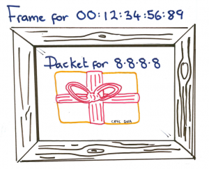
A pictoral representation of a packet in a frame

A packet, addressed by IP wrapped up in a frame, addressed by MAC address

So, in bullet point form, the facts needed for the rest of the blog post are:

  • Communication between two devices on the same network is at “layer 2”, addressed by MAC address using frames.
  • Communication between two devices on different networks is at “layer 3”, addressed by IP using packets.
  • Layer 3 packets are wrapped in layer 2 frames
  • For intra network communication, the IP of the packet and the MAC of the enclosing frame are for the same device
  • For inter network communication, the IP remains static for the entire route (ignoring NAT), but the MAC address changes for the next gateway device as it traverses networks.
  • ARP is the process to map IP addresses to MAC addresses
  • Knowledge of TCP is not needed for understanding this blog post.

Routing tables on Linux, what do they do?

If you fire up a Linux client, connect it to eduroam and run “ip route” at the terminal, you will see something similar to what I have:

default via 10.30.255.254 dev wlan0 proto static
10.30.248.0/21 dev wlan0 proto kernel scope link src 10.30.248.31 metric 2

This is about as simple a routing table as you could possibly get. It’s saying that everything not destined for the same host “localhost” (<alert type=”spoiler”>these routes are defined in another table </alert>) has two choices.

  • If it’s for a host on the network 10.30.248.0/21, then send it out the wlan0 interface with a source address of 10.30.248.31. This is layer 2 as no gateway is defined.
  • If it’s not for a host on this network, then send it out the wlan0 interface destined for the gateway 10.30.255.254. The gateway should know what to do with it. This is layer 3.

The Cisco wireless LAN controllers do something called client isolation so that anything for the network 10.30.248.0/21 except the gateway gets blocked, so in reality we only make use of the default rule (the other rule is used to find the gateway’s MAC address). Client isolation may not necessarily be true for some college and departmental deployments of eduroam, but the end result is the same; most traffic ends up at the gateway 10.30.255.254 and by complicated routing practices, it ends up on the NAT box to be routed to the outside world.

Let’s look at a possible routing table on the eduroam NAT boxes, with IP addresses changed slightly to protect the innocent and some additional routes removed:

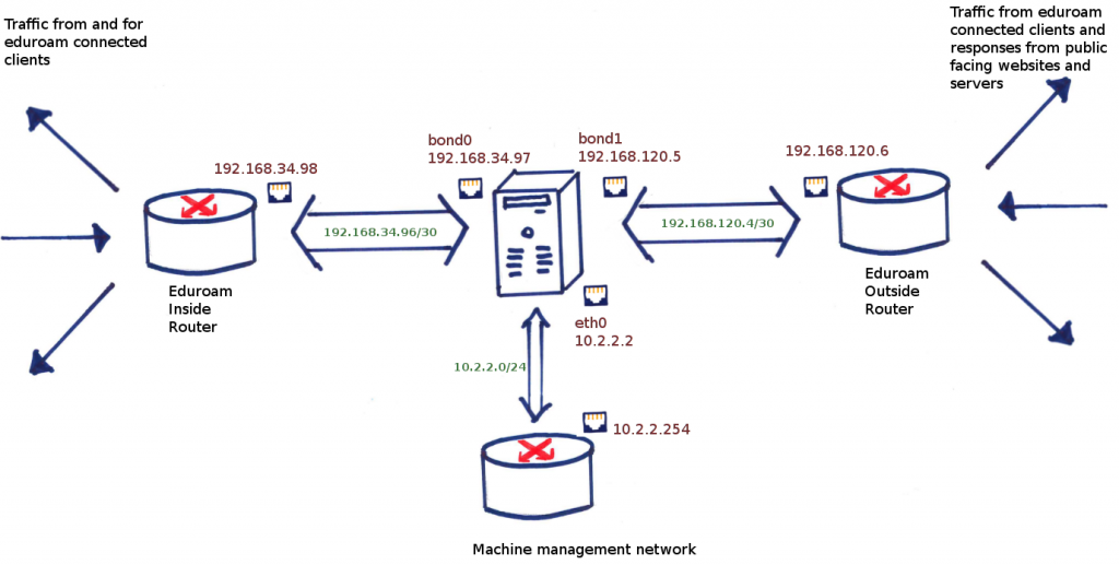
  • bond0 is the internal interface, facing the eduroam internal network. This has address 192.168.34.97
  • bond1 is the external interface, facing the outside world. This has address 192.168.120.5
  • eth0 is the management interface, facing the server room network, which has a gateway to the outside world as well. This has address 10.2.2.2. This is used for backups, logging, monitoring and SSH access.

Here is a pictorial representation of this:

A represenation of what the NAT box looks like in terms of its interfaces connected to networks

A representation of what the NAT box routing looks like

# ip route list
default via 192.168.120.6 dev bond1 
10.16.0.0/12 via 192.168.34.98 dev bond0 
10.2.2.0/24 dev eth0  proto kernel  scope link  src 10.2.2.2
192.168.120.4/30 dev bond1  proto kernel  scope link  src 192.168.120.5 
192.168.34.96/30 dev bond0  proto kernel  scope link  src 192.168.34.97

Let’s clean this up by removing the proto and scope definitions:

default via 192.168.120.6 dev bond1 
10.16.0.0/12 via 192.168.34.98 dev bond0 
10.2.2.0/24 dev eth0  src 10.2.2.2
192.168.120.4/30 dev bond1  src 192.168.120.5 
192.168.34.96/30 dev bond0  src 192.168.34.97

A packet is checked against the list from bottom to top, and the first rule that matches is the one used. The top rule, the one labelled “default”, is the catch-all and defines that we send everything out the bond1 interface via the gateway 192.168.120.6, and which eventually ends up on the janet router and then the outside world. When a reply comes in, the routing tables are consulted (after the NAT has already changed the destination to my private address 10.30.248.31) and it goes out the bond0 interface because of the second line in the list above. The “via 192.168.34.98” means that it is a route not on the current network so needs to go via the gateway 192.168.34.98. Eventually the return packet will end up at an eduroam client.

If you look again, you’ll see two networks 192.168.120.4/30 and 192.168.34.96/30. These are linknets that we use for incoming and outgoing traffic (the former is between the server and janet, the latter is between the server and the eduroam clients.) We have seen its use above in defining a gateway for the inside traffic (10.16.0.0/12) and they are the smallest possible multi-host networks that you can define (i.e. a network comprising 2 hosts). Each side of the link defines the other as the gateway for a particular subnet.

Why do I need to define linknets?

Let’s change the ip routes via the ip command to remove the use of a gateway.

# ip route change 10.16.0.0/12 dev bond0

# ip route list
default via 192.168.120.6 dev bond1 
10.16.0.0/12 dev bond0 
10.2.2.0/24 dev eth0  src 10.2.2.2
192.168.120.4/30 dev bond1  src 192.168.120.5 
192.168.34.96/30 dev bond0  src 192.168.34.97

Will this work? Well, that depends on how the other end is configured. If it is set up for proxying arp requests, the Linux box will send an ARP request to obtain the MAC address for a client, say 10.16.1.1 and the router at the other end will respond with its own MAC address, thinking along the lines of “what I’m sending is not correct, but if you send it to me anyway, I’ll deal with it so it doesn’t matter.” The frames containing the packets will be addressed to that MAC address, and the other end will recieve them happily.. If it’s not configured like that, then the router will not respond, because it doesn’t know what the MAC address for that IP is, the Linux box will not know where to send the packet and it ultimately gets dropped.

Let’s revisit what happens when arp proxying is turned on (which appears to be the default on Cisco 4500-X devices.) Now the box will work as intended, but for each and every address, the box does an ARP lookup and stores the result in its MAC table. For low levels of traffic this is fine, but once we get to 30,000 devices simultaneously connected (as we do sometimes on eduroam), this is a problem. The MAC table will be full, all with the same MAC address, that of the router at the other end of the cable.

How do I know this? Well regrettably I made a configuration error that escaped into the early deployments of the new eduroam. There is another way to fill the MAC table, and that is to configure the gateway as the address on the box itself, rather than the router’s address (in our example, the via would be 192.168.120.5). In this case we’ve effectively said that the next hop of the frame is localhost. The Linux kernel makes the best of a bad situation and treats this as communication at layer 2. In the early stages, everything looked good and traffic was flowing reasonably. However, as the number of connected clients grew, the problem manifested itself with sluggish response as the CAM table became full and had to be garbage collected.

You can see for yourself the MAC addresses for systems on your network with a simple command

$ ip neigh

I would have expected a list of 10 or at a pinch 20 entries. When I ran it on the server, it responded with a list of 1024 addresses, the default maximum.

The fix was relatively easy, just changing the next hop to the correct address fixed everything, but diagnosing the problem (i.e. getting to the point of knowing to run ip neigh)was a little harder. This is an example of what I saw in the kernel message buffer

[1026987.757575] net_ratelimit: 1875 callbacks suppressed

with no supplementary lines to hint at what those callbacks were. Online research suggested to me that this was a syslogging problem (i.e. syslog was generating too many log lines) which led me down the wrong path (the syslogging for this host is indeed intentionally very verbose). Fortunately, and I am gratefully indebted to him for his help, my friend Robert Bradley found an incident report describing the exact same symptoms. According to that report, it seems that the 3.10 kernel suppresses the important error message “Neighbour table overflow” (we use Debian Wheezy with a backported kernel for reasons to be expanded upon in a future blog post.)

Hello, syslog, are you there?

Let’s go back to the routing table shown above. There’s an elephant sized problem that hasn’t been addressed, involving an asymmetry in the routing. Our syslog messages are not reaching our central logging server.

If we look more closely at the routes above, you may spot the problem: our syslog server is on the machine room network (eth0) but the default route is out bond1. I should emphasize this has nothing to do with what interface the syslog daemon is listening on. It is perfectly entitled to listen on eth0 but reply on bond1, and in fact if it’s doing things according to the OSI model, it should not even know what interface it’s replying to because all it cares about is its application layer before handing the packet to the OS to deal with the lower layers.

We would like it to send traffic out eth0. We could patch the problem, by pushing traffic for the university out eth0, for example:

$ ip route add 129.67.0.0/16 via 10.2.2.254 dev eth0

But that’s no good either. What we’ve just done is push all traffic for the university out the eth0 interface. This is bad because people on eduroam should be connecting to university services as if they are external to the university (eth0 is on the university network) and, more practically, the eth0 has limited bandwidth because it’s just meant for server management. Fiddling with the address ranges in the above route only serves to mask an underlying design flaw.

VRF to the rescue

Virtual Routing and Forwarding (VRF) is where you have multiple routing tables, and which routing table you use is chosen based on properties of the packet to be routed. It could be the interface on which the packet came in on, the source address of the packet or some other criterion as we’ll discover later.

Looking at the diagram above we can construct a high level overview of what we want:

  1. Packets coming in for forwarding on bond0 can only leave on bond1
  2. Packets coming in on eth0 should never be forwarded
  3. Packets coming in for forwarding on bond1 should only leave bond0
  4. Packets generated by the host should only leave eth0

Rule 2 is easily sorted by iptables or sysctl, there is no need to add VRF to this. Rule 3 should already be sorted because once the replies have been translated to the private address range 10.16.0.0/12, there is already a rule to send that out bond0, and again anything else can be dropped. It is rules 1 and 4 that we need the second routing table for. In an ideal world, the default gateway should be out eth0 unless forwarding an eduroam packet, when its default gateway should be bond1.

Again, fire up your linux client and look at the file /etc/iproute2/rt_tables

$ cat /etc/iproute2/rt_tables
#                                                 
# reserved values
#    
255     local 
254     main
253     default
0       unspec

These are the names of routing tables, and it looks like there are some already. For reasons that I don’t understand, the default table is not the default one, and is in fact empty:

$ ip route list table default
$

The local one is set up by the kernel. You can look but don’t touch!

It’s the main one that has the routing table we know and love:

$ ip route list table main
default via 192.168.120.6 dev bond1 
10.16.0.0/12 via 192.168.34.98 dev bond0 
10.2.2.0/24 dev eth0  src 10.2.2.2
192.168.120.4/30 dev bond1  src 192.168.120.5 
192.168.34.96/30 dev bond0  src 192.168.34.97

The numbers next to the routing tables have to be unique for each table and have to be in the range 0 to 255 (because 256 VRFs ought to be enough for anybody.)

Let’s create one by appending to the rt_tables file

# echo 200 Eduroam-egress >> /etc/iproute2/rt_tables

and create a rule so that any packet coming in on bond0 for forwarding always uses this routing table

# ip rule add iif bond0 table Eduroam-egress

and finally, create only one route in that table, the default gateway

# ip route add default via 192.168.120.6 dev bond1 table Eduroam-egress

We can now change our “main” default route to go via eth0, so that SSH behaves as we would expect.

How does this work with our NAT setup? As described in a previous post, our rules are done in POSTROUTING, so the fate of the packet has been sealed by this point. Anything done by the NAT rules is done after the routing tables have been consulted. Implicit in this is that return traffic is translated back into its private address before routing table consultation, so that works as you would hope as well.

The rules created by ip command will only last as long as the system is up. Any reboots will flush any config (a boon if you’re testing your routing and have accidentally locked yourself out of your own SSH session, but not so great otherwise) so in our case we created scripts to persist our changes. You can define the routes using the /etc/network/interfaces command, but in our case, with daemons to start and stop with the interfaces, we found it easier to create a bash script bond0-if-up and have in our /etc/network/interfaces

auto bond0
iface bond0 inet static
        bond-slaves eth6 eth4
        address  192.168.120.5
        netmask  255.255.255.252
        bond-mode 802.3ad
        bond-miimon 100
        bond-downdelay 200
        bond-updelay 200
        bond-lacp-rate 1
        bond-xmit-hash-policy layer2+3
        txqueuelen 10000
        up   /etc/network/eduroam-interface-scripts/bond0-if-up
        down /etc/network/eduroam-interface-scripts/bond0-if-down

If we were using Debian Jessie (which is currently unreleased), its default init system systemd would be able to do this using much simpler dependency rules, but for the moment, these scripts running on interface up and down should suffice.

How configurable is Linux’s rt_tables?.

Asked another way, how fine-grained can you define which routing table to use? We are deciding the routing table based on the interface the packet for forwarding came in on. Can we go deeper? Well, this being Linux, it’s almost certainly more configurable than you need it to be. (As in the previous post’s section on ipset, the following is nothing I have tried myself. It may work as advertized. I wouldn’t advise doing this in anything other than a toy environment.)

A not often mentioned feature of iptables is the ability to mark a packet (tagging would be a more recognizable term for it.) Most systems administrators are familiar with ‘-j ACCEPT’, or ‘-j REJECT’, but there are more options (we have already seen ‘-j SNAT’.) One of these options is ‘-j MARK’. The following is an example

iptables -t mangle -A PREROUTING -s 10.16.0.0/12 -p tcp \
	-j MARK --set-mark 0x8
iptables -t mangle -A PREROUTING -s 10.16.0.0/12 -p udp \
        -j MARK --set-mark 0x4

Here we have defined two marks, one mark is assigned to traffic that is udp and the other is assigned to tcp traffic. What did that do? On its own absolutely nothing, but these marks can be used in conjunction with ip rules:

ip rule add fwmark 0x8 table tcp-packets
ip rule add fwmark 0x4 table udp-packets

Now, if the packets are tcp, they will be routed via the tcp-packets table, and if they’re udp, they’ll be routed by the other (so long as you have the tables defined in rt_tables as shown above.) What if the packet is neither tcp nor udp? In this case, there will be no mark assigned to the packet and it will use the main table.

We could get even sillier. The following would allow you to change the routing tables based on time of day.

iptables -t mangle -A PREROUTING -m time --timestart 09:00 \
    --timestop 18:00 -j MARK --set-mark 0x8
ip rule add fwmark 0x8 table working-hours

That should give some indication as to the flexibility of Linux routing tables.

What’s next

This concludes our look at Linux routing, next up will be an explanation of ether channel bonding.

Posted in eduroam | Tagged , | Comments Off on Linux and eduroam: Routing

Cisco networking and eduroam: Routing

This is the first post in a series discussing some of the finer details of the networking setup for the new eduroam infrastructure that went into production last month.

In this post, I will be covering the IP routing setup of the new networking infrastructure. This uses static routing & Virtual Routing & Forwarding instances (VRF) to get traffic from clients using the eduroam service out on to the Internet. Following on from this, I’ll explain the associated failover setup we opted for which uses the IOS ‘object-state tracking’ feature in a somewhat clever way for our active/standby setup.

What I won’t be covering here is how the traffic traverses the university backbone (from the FroDos) and is aggregated at a nominated egress (C) router within the backbone. This is because the mechanism for achieving this hasn’t actually changed much. It still uses the cleverness of the ‘Location Independent Network’ (LIN) system. I will mention briefly though that this makes use of VRFs, Multi-Protocol Label Switching (MPLS) and Multi-Protocol extensions to the Border Gateway Protocol (MP-BGP) to achieve this task. This allows us to provide LIN services (of which eduroam is one service) to many buildings around the collegiate university in a scalable way, whilst isolating these networks from others on the backbone.

Also omitted from this post are the details on how traffic from the Internet reaches our eduroam clients. Again, this is achieved in much the same way as before, using a combination of an advertising statement in our BGP configuration and some light static routing at the border for the new external eduroam IP range to get traffic to the new infrastructure.

So what are we working with?

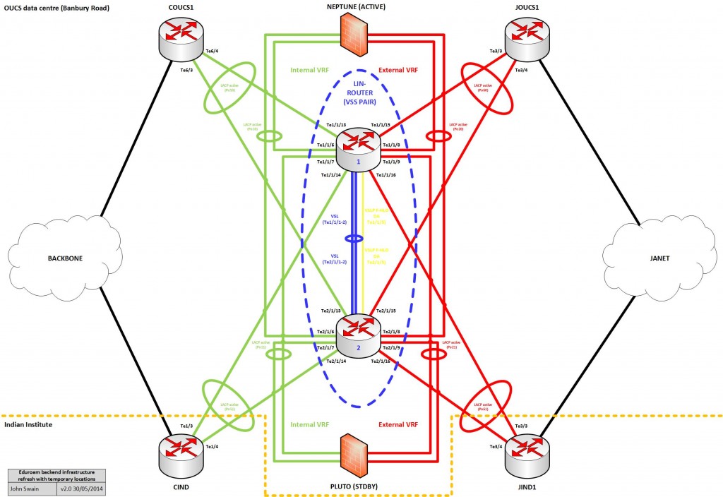
We procured two Cisco Catalyst 4500-X switches which run the IOS-XE operating system. For those not familiar with this platform, these are all SFP/SFP+ switches in a 1U fixed-configuration form-factor. As well as delivering the base L2/L3 features you’d normally expect from a switch, this platform also delivers some other cool features you might perhaps expect to find in a more advanced chassis-based form factor (at least in Cisco’s offerings anyway).

Specifically in the context of the new eduroam infrastructure, we’re using the Virtual Switching System (VSS) to pair these switches up to act as one logical router and also microflow policing for User Based Rate Limiting (UBRL). The latter of these features will be discussed at length in a later post. There are of course other features available within this platform which are noteworthy but I won’t be discussing them here.

Running VSS in any scenario has some obvious benefits, not least of which negating the need for any First-Hop Redundancy Protocol (FHRP) or Spanning-Tree Protocol (STP). It also allows us to use Multi-chassis EtherChannels (MECs) for our infrastructure interconnects. In non-Cisco speak, these are link aggregations that consist of member ports that each connect to a different 4500-X switch in our VSS pair.  For more information on the L1/L2 side of things, please see my previous post ‘Building the eduroam networking infrastructure’. All MECs have been configured in routed (no switchport) mode rather than in switching (switchport) mode. This makes the configuration far simpler in my opinion.

So with all this in mind, the diagram below illustrates how this looks from a logical point-of-view including some IP addressing we defined for the routed links in our new infrastructure:
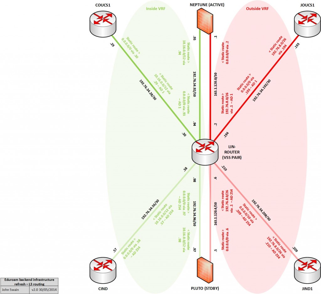
Eduroam-backend-refresh-L3-routing-2.0

Considering & applying the routing basics

OK, so with our network foundations built, we needed to configure the routing to get everything talking nicely.

Before I went gung ho configuring boxes, I thought it would be best to stand back and have a think about our general requirements for the routing configuration. At this point, it is noteworthy to mention that all Network Address Translation (NAT) in the design is handled externally by the Linux hosts in our infrastructure (my colleague Christopher has written an excellent post covering the finer points of NAT on Linux for those interested).

I summarised our requirements for the routing configuration as follows:

  1. Traffic from clients egressing the university backbone (addressed within the internal eduroam LIN service IP range 10.16.0.0/12) should have one default route through the currently active Linux host firewall. This is pre NAT of course and the routing for replies back to the clients should also be configured;
  2. Traffic from clients that makes it through the Linux host firewall egressing towards the Internet (NAT’d to addresses within the external eduroam IP range 192.76.8.0/26) should have one default route through the currently active border router. Once again, the routing for replies back to the clients should also be configured;
  3. Routing via direct paths (bypassing our Linux firewalls) should not be allowed;
  4. Ideally, the routing of management traffic should be kept isolated from normal data traffic.

With these requirements in mind, I started to consider technical options.

First of all, we decided to meet requirements 3 & 4 using VRFs. More specifically, what we would use is defined as a VRF ‘lite’ configuration – that is, separate routing table instances but without the MPLS/MP-BGP extensions. At this point, I would highlight that for the 4500-X platform, the creation of additional VRFs required the ‘Enterprise Services’ licence to be purchased and applied to each switch. This may not be the case with other platforms so if it’s a feature you ever intend to use, do ensure you check the licensing level required – of course I’m sure everyone checks these things first right?

To fulfil requirement 4, we would make use of the stock ‘mgmtVrf’ VRF built-in to many Cisco platforms (including the 4500-X) for the purpose of Out-Of-Band (OOB) management via a dedicated management port. This port is by default locked to this VRF anyway (so you can’t change its assignment even if you wanted to). We were forced down this route because there are no other built-in baseT ethernet ports on these switches to connect to our local OOB network – OK, we could have installed a copper gigabit SFP transceiver in one of the front-facing ports, but that would have been a waste considering the presence of a dedicated management port! I’ll avoid further discussion of this here as it’s outside the scope of this post. However I do intend to cover this topic in a later post as setting this up really wasn’t as easy as it should have been in my honest opinion.

So, I started with the following configuration to break up the infrastructure generally into two ‘zones’. One VRF for an ‘inside’ zone (university internal side) and another for an ‘outside’ zone (the Internet facing side):

vrf definition inside
  address-family ipv4
  exit-address-family
exit

vrf definition outside
  address-family ipv4
  exit-address-family
 exit

Note the syntax to create VRFs on IOS-XE is quite different to that of it’s IOS counterparts. In IOS-XE It is necessary to define address family configurations for each routed protocol you wish to operate (in a similar way to how you would do with a BGP configuration for example). In this scenario, we are only running unicast IPv4 (for now at least) so that’s what was configured. With our new VRFs established, it was then necessary to assign the appropriate interfaces to each VRF and give them some IP addressing. The example below depicts this process for two example interfaces – I simply rinsed and repeated as necessary for the others in the topology:

interface Port-channel50
 description to COUCS1
 no switchport
 vrf forwarding inside
 ip address 192.76.34.30 255.255.255.252
 no shut
 exit

interface Port-channel60
 description to JOUCS1
 no switchport
 vrf forwarding outside
 ip address 192.76.34.194 255.255.255.252
 no shut
 exit

With this completed for all interfaces, I verified the routing tables had been populated like so:

#Global table:
lin-router#sh ip route
<snip>
Gateway of last resort is not set

‘Inside’ VRF table:
lin-router#sh ip route vrf inside
<snip>

Gateway of last resort is not set

      192.76.34.0/24 is variably subnetted, 8 subnets, 2 masks
C        192.76.34.28/30 is directly connected, Port-channel50
L        192.76.34.30/32 is directly connected, Port-channel50
C        192.76.34.56/30 is directly connected, Port-channel51
L        192.76.34.58/32 is directly connected, Port-channel51
C        192.76.34.92/30 is directly connected, Port-channel10
L        192.76.34.94/32 is directly connected, Port-channel10
C        192.76.34.96/30 is directly connected, Port-channel11
L        192.76.34.98/32 is directly connected, Port-channel11

‘Outside’ VRF table
lin-router#sh ip route vrf outside
<snip>

Gateway of last resort is not set

      163.1.0.0/16 is variably subnetted, 4 subnets, 2 masks
C        163.1.120.0/30 is directly connected, Port-channel20
L        163.1.120.2/32 is directly connected, Port-channel20
C        163.1.120.4/30 is directly connected, Port-channel21
L        163.1.120.6/32 is directly connected, Port-channel21
      192.76.34.0/24 is variably subnetted, 4 subnets, 2 masks
C        192.76.34.192/30 is directly connected, Port-channel60
L        192.76.34.194/32 is directly connected, Port-channel60
C        192.76.34.208/30 is directly connected, Port-channel61
L        192.76.34.210/32 is directly connected, Port-channel61

This output confirms that I addressed the interfaces properly, assigned them to the correct VRFs and that they were operational (ie capable of forwarding). It also confirmed the presence of no routes in the global routing table which is what we wanted – isolation!

At this point though, it would still be possible to ‘leak’ routes between VRFs so to eliminate this concern, I applied the following command:

no ip route static inter-vrf

So we now have some routing-capable interfaces isolated within our defined VRFs. Next, we need to make things talk to each other!

Considering static routing vs dynamic routing

We needed a routing configuration to get some end-to-end connectivity between our internal eduroam clients and the outside world. This basically boiled down to one major question and fundamental design decision –  ‘Shall I define static routes or use a routing protocol to learn them?’ There are always pros and cons to either choice in my honest opinion.

Why? Well static routing is great in its simplicity and for the fact it doesn’t suck up valuable resources on networking platforms. It does however have the potential for laborious administrative overhead – especially if used excessively! In other words, it doesn’t scale well in some large deployments.

Dynamic routing via an Interior Gateway Protocol (IGP) can be a great choice depending on the situation and which one you choose. They reduce the need for manual administrative overhead when changes occur but this does come at a price. Routing protocols consume resources such as CPU cycles and require administrators to have a sound knowledge of their internal mechanisms and their intricacies when things go wrong. This can get interesting (or painful) depending on the problem scenario!

So I would suggest this decision comes to picking the ‘right tool for the right job’. As a general rule of thumb, I tend to work on the basis that large environments with many routes that change frequently probably need an IGP configuration. Everything else can usually be done with static routing.

Some history

Previously with the old infrastructure, we made use of the Routing Information Protocol version 2 (RIPv2) IGP to learn and propagate routes. I believe this was a design decision based on two main factors – I leave room for being wrong here though as it was admittedly before my time. I summarised these as:

  1. The need for two physical switches performing the routing for internal and external zones – This in itself would have mandated a larger number of static routes so an IGP configuration probably seemed like a more logical choice at the time;
  2. RIPv2 was the only IGP available using the IP base license on the Catalyst 3560 switches.

There could have been other reasons too of course. RIPv2 for those that don’t know is a ‘distance-vector’ routing protocol that uses ‘hop count’ as it’s metric.

RIPv2 communicated routes between the separate internal and external switches in the old topology through the active Linux firewall host. What this meant in production was that a loss of a link or the Linux host running the firewall resulted in a re-convergence of the routed topology to use the standby path. The convergence process when using RIPv2 is quite slow really and to initiate a failover manually (say you wanted to pull the Linux host offline to perform some maintenance for example) meant re-configuring an ‘offset list’ to manipulate the hop count of the routes to reflect your desired topology. Granted this all worked, but it felt a little clunky at times!

Static routing simplicity

For the new infrastructure, we don’t have two switches performing the routing (there are two switches but these are logically arranged as one with VSS). Instead we have logical separation with VRFs which equates to having two logical routers. With this design, there is no requirement for direct inter-VRF communication – instead our firewalls provide inter-VRF communication as required. This, coupled with the considerations above, ultimately led to a decision to use a static routing configuration over one based on dynamic routing with an IGP.

To elaborate further, the routing configuration in this new design really only requires two routes per VRF per path (ignoring the mgmtVrf). For the active path for example, these are:

#From eduroam clients to Linux firewall host:
ip route vrf inside 0.0.0.0 0.0.0.0 192.76.34.93

#From Linux firewall host to eduroam clients:
ip route vrf inside 10.16.0.0 255.240.0.0 192.76.34.29

#From eduroam clients (post-NAT)  to the Internet
ip route vrf outside 0.0.0.0 0.0.0.0 192.76.34.193

From the Internet to eduroam clients (post-NAT)
ip route vrf outside 192.76.8.0 255.255.255.0 163.1.120.1

So this is a very simple and lightweight static routing configuration really. OK, so it does get a little larger and more complicated with the failover mechanism and the standby path routes included, but not by much as you’ll see shortly. In total there are only ever likely to be a handful of routes in this configuration that are unlikely to change very frequently so the administrative overhead is negligible.

How shall we handle failures?

At this point, assuming we’d configured the routing as described and had added our standby routes in exactly the same fashion, what we’d have actually ended up with is an active/active type setup – at least from the networking point-of-view. This would have resulted in traffic through our infrastructure being load-balanced across all available routes via both firewall hosts.

Configuring the additional routes in this way might have been OK had these general caveats not been true of our firewall/NAT setup:

  • The NAT rules on both firewall hosts translate traffic sourced from internal (RFC1918) IP addresses into the same external IP address range;
  • The firewall hosts do not work together to keep track of the state of their NAT translation tables.

So at this point, my work clearly wasn’t done yet. In our scenario we were most certainly going to carry on with an active/standby setup (at least in the short-term).

I reached the conclusion that what was needed was a way to track the state of the active path to make sure that if a full or partial path failure occurred, a failover mechanism would ensure all traffic would use the secondary path instead.

Standby path routes

When I added these routes, I in fact configured them slightly differently. Specifically, I configured them with a higher Administrative Distance (AD) value.

To explain briefly, AD is assigned based on the source of the route. For instance, we can consider two sources in this context to be routes that have been statically configured, or ones that have been learned via an IGP for example. There are some default values IOS & IOS-XE assigns to each route source. AD only comes into play if you have more than one exactly matching candidate route to a destination (of the same prefix length) offered to the routing table from different sources. The one with the lowest AD in this situation wins and is then installed in the routing table.

You can view the AD value currently assigned to a route by interrogating the routing table. For example, let’s look at the static routes in the inside VRF routing table:

lin-router#sh ip route vrf inside static

<snip>

Gateway of last resort is 192.76.34.93 to network 0.0.0.0

S*    0.0.0.0/0 [1/0] via 192.76.34.93
      10.0.0.0/12 is subnetted, 1 subnets
S        10.16.0.0 [1/0] via 192.76.34.29

I’ve highlighted the AD values in bold in the output for illustration purposes. You can see the default AD value of ‘1’ is applied to these routes. The second value is the ‘metric’ of the route, in the case of the two routes shown here, the next-hop is connected to the router so this is ‘0’.

So in the case of our standby routes, I assigned an AD value  of ‘254’ to the standby routes. This was achieved using the following commands:

#From eduroam clients to Linux firewall host:
ip route vrf inside 0.0.0.0 0.0.0.0 192.76.34.97 254

#From Linux firewall host to eduroam clients:
ip route vrf inside 10.16.0.0 255.240.0.0 192.76.34.57 254

#From eduroam clients (post-NAT) to the Internet
ip route vrf outside 0.0.0.0 0.0.0.0 192.76.34.209 254

From the Internet to eduroam clients (post-NAT)
ip route vrf outside 192.76.8.0 255.255.255.0 163.1.120.5 254

You may see the creation of static routes with an artificially high AD value sometimes referred to as creating ‘floating’ routes. They can be considered to float because they will never be installed in the routing table (or sink if you will) provided that matching routes with a better (lower) AD value have already been installed. So our standby path routes will now be offered to the routing table in the event the active ones disappear for any reason.

At this point, I noted that we could still end up in a situation where a new path made up of a hybrid of both active and standby links could be selected. In our scenario, I feared this could result in undesired asymmetric routing and make traffic paths harder to predict. What I really wanted was an easily predictable path every time regardless of where a failure occurred or the nature of such a failure.

Introducing IOS ‘object-state tracking’

The object-state tracking feature does pretty much what the name implies. You configure a tracking object to check the state of something – be it an interface’s line protocol status or a static route’s next hop reachability for instance. The two possible states can either be ‘up’ or ‘down’ and depending on the configuration you apply and a change in state can trigger some form of action.

What to track and how to track it

It was clear that what was needed was a way to track each of our directly connected links making up our active path. To re-cap, these are:

‘Inside VRF’

  • C       192.76.34.28/30 is directly connected, Port-channel50
  • C       192.76.34.92/30 is directly connected, Port-channel10

‘Outside VRF’

  • C       163.1.120.0/30 is directly connected, Port-channel20
  • C       192.76.34.192/30 is directly connected, Port-channel60

To start with, I decided to map these to separate tracking-objects using the following configuration:

track 2 ip route 192.76.34.92 255.255.255.252 reachability
 ip vrf inside
 delay down 2 up 2

track 3 ip route 192.76.34.28 255.255.255.252 reachability
 ip vrf inside
 delay down 2 up 2

track 4 ip route 163.1.120.0 255.255.255.252 reachability
 ip vrf outside
 delay down 2 up 2

track 5 ip route 192.76.34.192 255.255.255.252 reachability
 ip vrf outside
 delay down 2 up 2

One potential gotcha to watch for when configuring tracking objects for routes/interfaces assigned within VRFs is that it is also necessary to define the VRF in the object itself. If you don’t, you’ll likely find that your object will never reach an up state (because the entity being tracked doesn’t exist as far as the global routing table is concerned). I admit, I got caught out by this the first time around!

Note that an alternative strategy I could have chosen would have been to monitor the line protocol of the interfaces involved. There is a good reason I didn’t configure the objects this way. This is basically because it’s inherently possible for the line protocol of the interfaces to stay up but there be other issues causing an IP to be unreachable. I therefore figured tracking reachability would be the safest and most reliable option for our scenario.

Also delay up/down values (in seconds) have been defined. These just add a delay of 2 seconds whenever the state of one of the objects changes from up->down or down->up. I’ll explain this further in the context of our failover mechanism shortly.

Tying the tracking configuration together with the other elements

At this point, the configuration gets a bit more interesting (at least in my view). What I wasn’t originally aware of is that it’s possible to in effect ‘nest’ a list of tracking objects within another tracking object. Therefore to meet our requirements, I created another tracking object (the ‘parent’) to track the objects I created earlier (the ‘daughters’):

track 1 list boolean and
 object 2
 object 3
 object 4
 object 5
 delay down 2 up 2

This configuration allows us to track the state of many daughter objects. If one of these ever reaches the ‘down’ state, this also causes the parent tracking object to follow suit using the ‘boolean and’ logic parameter.

With the object-tracking configuration completed, I proceeded to amend the static route configuration for the active path to make use of the parent tracking object:

#Removing previous static routes for active path:
no ip route vrf inside 0.0.0.0 0.0.0.0 192.76.34.93
no ip route vrf inside 10.16.0.0 255.240.0.0 192.76.34.29
no ip route vrf outside 0.0.0.0 0.0.0.0 192.76.34.193
no ip route vrf outside 192.76.8.0 255.255.255.0 163.1.120.1

#Re-adding static routes with reference to parent tracking object:
ip route vrf inside 0.0.0.0 0.0.0.0 192.76.34.93 track 1
ip route vrf inside 10.16.0.0 255.240.0.0 192.76.34.29 track 1
ip route vrf outside 0.0.0.0 0.0.0.0 192.76.34.193 track 1
ip route vrf outside 192.76.8.0 255.255.255.0 163.1.120.1 track 1

What this gives us is a mechanism that will remove *all* the active path static routes if any one, many or all of the directly connected active links fails. The cumulative delay between an object state change (and therefore when any routing table change will occur) in our scenario should be:

daughter_object_delay + parent_object delay = total delay time.

So that’s:

2 + 2 = 4 seconds of total delay time.

You might be wondering why I configured these particular delay values on the objects, or even why I bothered delay times at all. Well, I did so in an effort to guard against the possibility of the state of an object rapidly transitioning.

Why could this be an issue? Well in our scenario here, it could result in routing table ‘churn’ (routes rapidly being installed and withdrawn from the routing table) which in-turn could have a negative impact on the performance of the switches. Frankly, I don’t see this being a likely occurrence and even if it did, I’m not sure it would be enough to drastically impact the performance of the switches (especially in light of their relatively high hardware specification) but the rapid state transitioning could be possible, say for instance, if a link were to flap (go up and down rapidly) because of an odd interface or transceiver fault. It’s probably best to think of these values and their configuration as a kind of insurance policy.

Generally, I think the resulting failover time of approximately 5 seconds is acceptable in this scenario and is certainly going to be an improvement over what we would have experienced with the old infrastructure using RIPv2.

Does it work?

Yes it does and to prove the point, I’ll demonstrate this using an identical configuration I ‘labbed up earlier’ in our development environment. Rest assured, it’s been tested in our production environment too and we’re confident it works in exactly the same way as what’s shown below.

Here’s some output from the ‘show track’ command illustrating everything in a working happy state:

Rack1SW3#show track
Track 1
  List boolean and
  Boolean AND is Up
    112 changes, last change 2w5d
    object 2 Up
    object 3 Up
    object 4 Up
    object 5 Up
  Delay up 2 secs, down 2 secs
  Tracked by:
    STATIC-IP-ROUTINGTrack-list 0
Track 2
  IP route 192.76.34.92 255.255.255.252 reachability
  Reachability is Up (connected)
    106 changes, last change 2w5d
  Delay up 2 secs, down 2 secs
  VPN Routing/Forwarding table "inside"
  First-hop interface is Port-channel10
Track 3
  IP route 192.76.34.28 255.255.255.252 reachability
  Reachability is Up (connected)
    2 changes, last change 12w0d
  Delay up 2 secs, down 2 secs
  VPN Routing/Forwarding table "inside"
  First-hop interface is Port-channel48
Track 4
  IP route 163.1.120.0 255.255.255.252 reachability
  Reachability is Up (connected)
    96 changes, last change 2w5d
  Delay up 2 secs, down 2 secs
  VPN Routing/Forwarding table "outside"
  First-hop interface is Port-channel20
Track 5
  IP route 192.76.34.192 255.255.255.252 reachability
  Reachability is Up (connected)
    4 changes, last change 12w0d
  Delay up 2 secs, down 2 secs
  VPN Routing/Forwarding table "outside"
  First-hop interface is Port-channel47

So you can see that aside from the interface numbering used in the development environment, the configuration used is the same.

I’ll simulate a failure of the inside link between the router and our active Linux firewall host by shutting down the associated interface (Port-channel10). I’ve also enabled debugging of tracking objects using the ‘debug track’ command which simplifies the demonstration and saves me the effort of manually interrogating the routing table or the tracking object to verify that the change took place:

Rack1SW3#conf t
Rack1SW3(config)#int po10
Rack1SW3(config-if)#shut
Rack1SW3(config-if)#
^Z
Rack1SW3#
*May 24 04:35:39.488: %LINEPROTO-5-UPDOWN: Line protocol on 
Interface Port-channel10, changed state to down
Rack1SW3#
*May 24 04:35:40.452: %LINK-5-CHANGED: Interface FastEthernet1/0/9, 
changed state to administratively down
*May 24 04:35:40.469: %LINK-5-CHANGED: Interface FastEthernet1/0/10, 
changed state to administratively down
*May 24 04:35:40.478: %LINK-5-CHANGED: Interface Port-channel10, 
changed state to administratively down
*May 24 04:35:41.459: %LINEPROTO-5-UPDOWN: Line protocol on 
Interface FastEthernet1/0/9, changed state to down
Rack1SW3#
*May 24 04:35:41.476: %LINEPROTO-5-UPDOWN: Line protocol on 
Interface FastEthernet1/0/10, changed state to down
Rack1SW3#
*May 24 04:35:52.364: Track: 2 Down change delayed for 2 secs
Rack1SW3#
*May 24 04:35:54.369: Track: 2 Down change delay expired
*May 24 04:35:54.369: Track: 2 Change #109 IP route 192.76.34.92/30, 
connected->no route, reachability Up->Down
*May 24 04:35:54.797: Track: 1 Down change delayed for 2 secs
Rack1SW3#
*May 24 04:35:56.802: Track: 1 Down change delay expired
*May 24 04:35:56.802: Track: 1 Change #115 list, boolean and 
Up->Down(->30)

OK, so we can see above that the Port-channel went down. I’m representing the backup path in my development scenario using loopback interfaces and floating routes have been configured using these pretend links. These routes should now have been installed in the routing table so to verify this, I checked which next-hop interface was being selected for some example destinations within each of the VRFs using the ‘show ip cef’ command:

Rack1SW3#sh ip cef vrf inside 10.16.136.1
10.16.0.0/12
  nexthop 192.76.34.57 Loopback20

Rack1SW3#sh ip cef vrf inside 8.8.8.8
0.0.0.0/0
  nexthop 192.76.34.97 Loopback10

Rack1SW3#sh ip cef vrf outside 192.76.8.1
192.76.8.0/26
  nexthop 163.1.120.5 Loopback40

Rack1SW3#sh ip cef vrf outside 8.8.8.8
0.0.0.0/0
  nexthop 192.76.34.209 Loopback30

So this looks to work for our pretend failure scenario, but will it recover? To find out, I brought interface Port-channel10 back up:

Rack1SW3(config)#int po10
Rack1SW3(config-if)#no shut
Rack1SW3(config-if)#
^Z
Rack1SW3#
*May 24 04:37:39.411: %LINK-3-UPDOWN: Interface Port-channel10, 
changed state to down
*May 24 04:37:39.411: %LINK-3-UPDOWN: Interface FastEthernet1/0/9, 
changed state to up
*May 24 04:37:39.411: %LINK-3-UPDOWN: Interface FastEthernet1/0/10, 
changed state to up
Rack1SW3#
*May 24 04:37:43.832: %LINEPROTO-5-UPDOWN: Line protocol on 
Interface FastEthernet1/0/9, changed state to up
*May 24 04:37:44.075: %LINEPROTO-5-UPDOWN: Line protocol on 
Interface FastEthernet1/0/10, changed state to up
Rack1SW3#
*May 24 04:37:44.830: %LINK-3-UPDOWN: Interface Port-channel10, 
changed state to up
*May 24 04:37:45.837: %LINEPROTO-5-UPDOWN: Line protocol on 
Interface Port-channel10, changed state to up
Rack1SW3#
*May 24 04:37:52.422: Track: 2 Up change delayed for 2 secs
Rack1SW3#
*May 24 04:37:54.427: Track: 2 Up change delay expired
*May 24 04:37:54.427: Track: 2 Change #110 IP route 192.76.34.92/30, 
no route->connected, reachability Down->Up
*May 24 04:37:54.720: Track: 1 Up change delayed for 2 secs
Rack1SW3#
*May 24 04:37:56.725: Track: 1 Up change delay expired
*May 24 04:37:56.725: Track: 1 Change #116 list, boolean and 
Down->Up(->40)

I then repeated my previous show ip cef  tests:

Rack1SW3#sh ip cef vrf inside 10.16.136.1
10.16.0.0/12
  nexthop 192.76.34.29 Port-channel48

Rack1SW3#sh ip cef vrf inside 8.8.8.8
0.0.0.0/0
  nexthop 192.76.34.93 Port-channel10

Rack1SW3#sh ip cef vrf outside 192.76.8.1
192.76.8.0/26
  nexthop 163.1.120.1 Port-channel20

Rack1SW3#sh ip cef vrf outside 8.8.8.8
0.0.0.0/0
  nexthop 192.76.34.193 Port-channel47

Great! So failure and recovery scenarios have tested successfully.

Final thoughts

I am generally very pleased with the routing and failover solution that’s been built for the new infrastructure. I think of particular benefit is its relative simplicity, especially when compared with the mechanisms used in the previous infrastructure.

It’s also much easier to initiate a failover with this new mechanism say if for some reason you specifically wanted the standby path to be used instead of the active one. This can be useful for carrying out any configuration changes or maintenance work on one of the Linux hosts for instance. This can either be executed by shutting down an interface on the host, or one on the switch within the active path. Then in around 5 seconds, hey presto! Traffic starts to flow over the other path!

Configuring an active/active scenario in the longer-term may be a better way forward ultimately. I’ve had some thoughts on using Policy-Based Routing (PBR) on the networking side to manipulate the next-hop of routing decisions based on the internal client source IP address. When used in conjunction with two distinct external NAT pool IP ranges (one per firewall host) this could be just the ticket to achieve a workable active/active scenario. Time-permitting, I’ll be looking to test this within our development environment before contemplating this for production service. Assuming it worked OK in testing, I think it would also be worth weighing up the time and effort that this configuration would involve against the relative benefits and risks to the service.

That concludes my coverage on the routing/failover setup for the networking-side of the new eduroam back-end infrastructure. Thanks for reading!
Posted in Cisco Networks, eduroam | Comments Off on Cisco networking and eduroam: Routing

Linux’s role in the new eduroam infrastructure

People within Oxford University may be aware that the eduroam service has recently been upgraded to increase its bandwidth, which was saturated on the old infrastructure. This included the replacement of two Linux servers which provide services key to the successful running of eduroam. Much of what was done involved porting the old setup to new hardware, but we took the opportunity to improve the resiliency and tie up a few loose ends. This series of blog posts will seek to explain our new setup, some hurdles that we encountered while upgrading and some useful guiding blog posts and documentation we used.

The upgrade included an upgrade of the switches that sit either side of the Linux boxes (from two independent Cisco 3560 switches to two Cisco Catalyst 4500-X switches set up as a VSS pair) they warrant a series of posts of their own, which are being written by John Swain, and are being published concurrently with this series. There will be some overlap in the coverage but you may read either series in isolation, depending on what interests you.

The setup

Eduroam is a location independent service; whether you’re sat in the Bodleian library or in the John Radcliffe hospital, when you connect to the eduroam wireless SSID, the traffic generated eventually ends up going through one of two Linux servers (configured as an active/standby pair) which NAT the traffic, and route it via some dedicated networking infrastructure and onwards via janet to its destination. For a network the size of Oxford University’s eduroam, this is quite a feat in itself that I can claim absolutely no credit for (it was like that when I got here.)

The Linux servers’ roles in all of this are the following:

  • NAT – eduroam clients are assigned private IP addresses and so they need to be translated to a public IP before being given to janet.
  • DHCP – eduroam clients need unique addresses. One of a DHCP server’s roles is to ensure this is true by assigning addresses uniquely per client connected.
  • DNS – resolving a hostname (e.g. www.ox.ac.uk) to an IP address. This isn’t currently done by these boxes but they may do it in the future.
  • Logging – we log connections to assist with cease and desist requests.

NAT is the primary focus of this first blog post.

Network Address Translation

What is it?

The IP address assigned to an eduroam client is from an RFC1918, or private, address range. An example is 10.16.1.1 which can be found on the network 10.16.0.0/23. This means that while the client can in theory talk to other clients on the same range, for example 10.16.1.2, access to external sites, such as www.google.com, www.bbc.co.uk and even www.ox.ac.uk is not possible. What the client needs is a public IP address so that when it talks to the outside world’s public IP addresses, the outside world knows where to send a reply. In an ideal world everyone would have a unique public address, but this isn’t an ideal world. There are 4.3 billion IP addresses to be shared amongst 7 billion people and until a new IP standard comes along (IPv6 is just around the corner, and has been for years) we will have to make do with sharing public IPs so multiple private addresses use the same public address. It is the job of a Network Address Translation (NAT) server to translate a range of private addresses (e.g. 10.16.1.1, 10.16.1.2) to a public (e.g. 192.76.8.1) address. When you contact an external site, such as www.ox.ac.uk, the NAT server translates your address from private to public, and hands the request to www.ox.ac.uk.

A schematic diagram of the flow of traffic from an eduroam client to the outside world

A client making a request on eduroam

The www.ox.ac.uk web server replies, sending the reply to the NAT server, which translates the address back to the private one and you eventually get back the response to the original request.

The reply received by an eduroam client

The response from an external host

Some people might point out that I have just described PAT (port address translation) rather than NAT because NAT is not strictly address sharing. To those people I would say that you are correct, but I will still be referring to it as NAT for the remainder of this post as the meanings have become so blurred that not many people would be able to make the distinction.

Initial setup – Turning on packet forwarding.

Linux does not forward packets by default, which is what we require it to do. That is to say a Linux box will only accept packets if they are destined for the box itself. The following command will turn packet forwarding on:

echo "1" > /proc/sys/net/ipv4/ip_forward

Adding the line to your rc.local will mean that forwarding will be on the next time you reboot (otherwise it will reset.) We do things slightly differently for our NAT server, but only for historical reasons and the end result is the same as using the line above.

How can you implement it?

Most people implement NAT on Linux using iptables rules, a userspace frontend to the Linux kernel’s netfilter framework. When people talk of iptables, they usually are referring to its IP packet filtering capabilities. However, iptables can do much more, from NAT as we are doing here to even editing the packet header to implement some form of QoS.

In most small scale NAT deployments, the server has two addresses, one on the “inside” (usually on a private address range), the other on the “outside” (usually a public address). The private address is the gateway used by the clients, so traffic not for the current network ends up on the NAT box. This will be the lion’s share of the traffic. For example, a NAT box which has an address of 10.16.1.254 on its eth0 interface (the private network in this instance could be 10.16.0.0/23) and a public address of 192.76.8.1 connected via eth1. A simple rule on the NAT server so that clients on the 10.16.0.0/23 network can connect to the outside world would then be:

iptables -t nat -A POSTROUTING -s 10.16.0.0/23 -o eth1 -j MASQUERADE
A diagram of how masquerade works with respect to ethernet ports

What happens when you use MASQUERADE

I will not be explaining the individual flags required for iptables. The iptables man pages are very good and searching through them for things such as “POSTROUTING” and “-s” will explain their purpose very clearly.

Now, assuming that your routing to, from and in the NAT box is correct (routing using Linux will be covered in a later post), if a laptop with an IP address of 10.16.1.1 attempts a connection to www.ox.ac.uk, the packets would be end up on the NAT server. The NAT server would then change the source address from 10.16.1.1 to 192.76.8.1 and send it out its public interface (eth1). The request would reach the Oxford University webserver, which would reply to the NAT server thinking it was that server that made the request. The NAT box, knowing better will receive the reply destined for 192.76.8.1, translate it back to 10.16.1.1 and forward it to the eduroam connected device.

How does the Linux kernel know that a particular reply from www.ox.ac.uk addressed to 192.76.8.1 needs to be rewritten to 10.16.1.1 and not 10.16.1.2? A full answer is going to be in a follow-up post but in short, Linux has a connection tracking system, called conntrack.

What’s the problem with this implementation?

While this will work in most environments, there is a limitation: Since our records have shown over 30,000 devices connected simultaneously in the past, there is real possibility of exhausting a single public IP’s 65535 source ports (ignoring the messy possibility of port overloading, where two connections share the same public IP address and source port.)

What our eduroam NAT implementation should do is use a range of addresses for the translated source address. In our case we have allocated 192.76.8.0/26 for the purpose.

Kernels up to 2.6.10 allowed for the following line which specifies a range of addresses to which the traffic can be translated:

# Don't do this
iptables -t nat -A POSTROUTING -s 172.16.1.0/24 -o eth1 -j SNAT \
    --to-source 192.76.8.1-192.76.8.62

This isn’t allowed any more, and for good reason. Some programs assume that consecutive connections from the same client have the same public IP address. This isn’t guaranteed with the line above. One time I may have the address 192.76.8.2, another I may have 192.76.8.4. In other words, the source address as seen by the external host is non deterministic.

I should note at this point that in the simple example above using MASQUERADE, the address 192.76.8.1 was an address that the Linux host had assigned to its interface (running “ip addr list” would have shown that address). Any traffic destined for 192.76.8.1 will not be forwarded unless the connection was started by a computer on the private address range. In other words, packets addressed to 192.76.8.1 can be terminated on the server itself. However, in the case of NAT traffic, the kernel’s connection tracking will kick in and know that the packets need to be forwarded. For our actual real world example below, the address range 192.76.8.0/26 is not on the host at all. The packets end up on the host by static routing and when they end up on the Linux box, they will be forwarded by default, stopped only by whatever rules you have in place in your FORWARD iptables chain.

Using an address range is the obvious solution, but there are a few things that you need to worry about:

  • Predictability: When you’re connected to the network, you don’t want your public IP as seen by the outside world to change regularly.
  • Load sharing: The public ip addresses should be utilized as evenly as possible.

These requirements seem obvious. The first requirement effectively necessitates that the mapping is based on private source IP. Splitting up the source IPs into evenly utilised sets of IPs (not necessarily subnets) to satisfy the second requirement is what the remainder of this post is about.

The u32 iptables module

To skip to the punchline, here is a snippet from our NAT configuration:

iptables -A POSTROUTING -s 10.16.0.0/12 -o bond1 -m u32 \
    --u32 "0xc&0xff=0xeb:0xef" -j SNAT --to-source 192.76.8.48
iptables -A POSTROUTING -s 10.16.0.0/12 -o bond1 -m u32 \
    --u32 "0xc&0xff=0xf0:0xf4" -j SNAT --to-source 192.76.8.49

Ignore the -o bond1 for a moment (that is link aggregation, a topic for another post). The eduroam address range, as shown above, is 10.16.0.0/12. This means that at any one time we have the potential to have over 1,000,000 clients connected. In practice we don’t as the IP allocations are subdivided based on various criteria (the college or department, for example), but the result is that some portions of this address space are fairly densely populated while others are unused. Splitting up the /12 subnet into smaller subnets would thus be unworkable as we would create hotspots.

For example, if we’d written something like

iptables -A POSTROUTING -s 10.16.0.0/16 -o bond1 -j SNAT \
    --to-source 192.76.8.48
iptables -A POSTROUTING -s 10.17.0.0/16 -o bond1 -j SNAT \
    --to-source 192.76.8.49

and the 10.17.0.0/16 network is unused, we would have wasted a precious public IP address.

A much better mechanism for sharing the traffic evenly on our eduroam addressing scheme is by the last octet, so x.x.x.1 is translated to one source IP address, while x.x.x.8 is translated to another.

Going back to our example lines, the important bit to notice is the fairly cryptic ‘--u32 "0xc&0xff=0xeb:0xef"' What we are doing here is we are using the u32 module of iptables, which allows you to create rules based on the contents of any consecutive 32 bits (or part thereof) of an IP packet. The source IP address is located 12 bytes into the header (which in hexidecimal [hex] notation is “c”). The u32 module then extracts the next 32 bits (aka 4 bytes), but since we only care about the last byte of the source IP (an IPv4 address takes up 4 bytes), we mask the rest so that they are 0. We then check to see if they are in the range eb to ef, or 235 to 239 in decimal notation.

Rewriting the rule in something more friendly to perl programmers, we would have

# By default, perl works at the character level. We 
# want substr to extract at byte boundaries.
use bytes;

# Extracting the $SOURCE_IP from the packet using
# the u32 module cannot really be represented
# in perl code. This is an attempt to convey what it might
# look like. This takes 4 bytes out of $IP_PACKET, starting
# at the 0xc byte.
$SOURCE_IP = substr $IP_PACKET, 0xc, 4;

# The 0xff in the iptables rule above would perhaps
# become clearer if written explicitly showing what bits
# it is masking (i.e. setting to zero.)
$LAST_OCTET_MASK = 0x000000ff;

# When you bitwise AND two numbers, you put the two numbers on top
# of each other (in binary notation), note when two 1 digits
# align, and make that digit in the output 1. Otherwise it's 0.
#
# For our example, our two input numbers are the $SOURCE_IP and
# $LAST_OCTET_MASK which when bitwise ANDed,
# create a number that every bit in the $SOURCE_IP
# is set to zero except the last octet. For example, here
# is an IP address of 12.34.56.78:
#
#  0x000000ff <= $LAST_OCTET_MASK
# &0x12345678 <= $SOURCE_IP
#  ==========
#  0x00000078
# 
# The numbers are written in hex here but the principle is the
# same: when it's an f in the $LAST_OCTET_MASK, the result contains
# the digit of the other row. If it's 0, then the result's digit
# is 0 as well, regardless of what is in the $SOURCE_IP.
$LAST_OCTET = $SOURCE_IP & $LAST_OCTET_MASK;

# The IP rule matches if the last octet is between
# the two ranges. The match_iptables_rule() is again a 
# representation of the -j SNAT .... 
match_iptables_rule() if $LAST_OCTET >= 0xeb and $LAST_OCTET <= 0xef;

Are there other ways of doing it?

Absolutely!

ipset

Be warned that the following is what I would have done. I haven’t actually tested this and while I don’t foresee the following not working for us, I wouldn’t say with any confidence that what I’ve written would work without modification.

The ipset module is traditionally used (to great effect) to collapse a long list of similar rules. Say you wanted to recreate the NAT scheme above, only using vanilla iptables rules (i.e. no modules.) It would look something like (simplified for brevity.)

iptables -A POSTROUTING -s 10.16.0.1 -j SNAT --to-source 192.76.8.1
iptables -A POSTROUTING -s 10.16.1.1 -j SNAT --to-source 192.76.8.1
iptables -A POSTROUTING -s 10.16.2.1 -j SNAT --to-source 192.76.8.1
...
iptables -A POSTROUTING -s 10.16.255.1 -j SNAT --to-source 192.76.8.1
iptables -A POSTROUTING -s 10.16.0.2 -j SNAT --to-source 192.76.8.1
iptables -A POSTROUTING -s 10.16.1.2 -j SNAT --to-source 192.76.8.1
iptables -A POSTROUTING -s 10.16.2.2 -j SNAT --to-source 192.76.8.1
...
iptables -A POSTROUTING -s 10.16.255.7 -j SNAT --to-source 192.76.8.1
iptables -A POSTROUTING -s 10.16.1.8 -j SNAT --to-source 192.76.8.2
.....

In total, there would be one rule per source IP address, or 1048574 rules. The person with IP address 10.31.255.254 would have reason to be annoyed because every packet from that address would have to be checked on each rule, causing significant delay in the processing of the packet (iptables rules are checked in sequence until the first match.)

Of course in reality nobody would be crazy enough to do this, but the same effect can be achieved using ipset. First, you create some sets

ipset -N octets-1-to-7  iphash
ipset -N octets-8-to-14 iphash
...

Then you add the relevant addresses to the set

# Script to add ip addresses to sets. In reality you would use
# "ipset restore", but that is harder to read, so in the interests
# of clarity the following adds IP addresses to sets individually

for second_octet in $(seq 16 31); do
 for third_octet in $(seq 0 255); do

  for fourth_octet in $(seq 1 7); do
   # Add IP address 10.$second_octet.$third_octet.$fourth_octet
   # to ipset octets-1-to-7
   ipset -A octets-1-to-7 10.$second_octet.$third_octet.$fourth_octet
  done

  for fourth_octet in $(seq 8 14); do
   ipset -A octets-8-to-14 10.$second_octet.$third_octet.$fourth_octet
  done

  # Same for other sets
  ...
 done
done
...

You then add the line in your iptables

iptables -t nat -A POSTROUTING -m set --set last-octet-1-to-7 src \
    -j SNAT --to-source 192.76.8.1
iptables -t nat -A POSTROUTING -m set --set last-octet-8-to-14  src \
    -j SNAT --to-source 192.76.8.2
...

Now you might wonder what you’ve gained here. At first glance it looks like all you’ve done is move an IP match in iptables into a match in ipset. In one sense, that is exactly what has happened, but the key here is the word “iphash” when we created the sets. This means that the IP addresses are stored in a hash table and looking up any one IP address for membership of the set is quick, independent of the IP address being matched, and more importantly the number of IP addresses in the set (within reason).

This method has the advantage over u32 in that you have ultimate control over your source based NAT tables. Don’t want to NAT an address when the last octet is a prime number? Sure, just write that into the script above! Is a public IP too heavily utilized? Not a problem, just move some IPs around from one set to another. There wouldn’t even be any downtime as updates to the ipset sets are atomic unlike lengthy iptables builds which can take a noticeable amount of time.

There are two downsides, although both are minor. The first one is that it takes up memory, but, as a very rough calculation, an IP address is 4 bytes, so to store every IP address in the eduroam network in memory would take roughly 4MB, or 3.8 × 10⁻⁷ Libraries of Congress. The ipset command can tell you how much memory it uses for each set created, which shows that if we were to use this, its memory usage wouldn’t be too far off this figure (14MB on our development server). The second one is that it takes a little time to build the hash tables. Again on our development server, it takes around 17 seconds to load all ip addresses in the 10.16.0.0/12 range (by using ipset restore < ipset-file. Using the script above would take over an hour.) Whether you’re happy with that depends on how long you’re happy to wait after every reboot.

Starting with a clean slate, I would probably have picked the ipset module over the u32 module. The main advantage that the u32 module has was that it was already in use on the old eduroam servers so less had to be done to get that working. Why u32 was chosen over ipset for the original eduroam implementation is not a question I can definitively answer but it would most likely be because the ipset module was not as widely known (it certainly wasn’t in the Debian repository) during the initial eduroam deployment.

What’s next?

This concludes a brief overview of NAT and its role in eduroam. Next up is a post on routing tables.

Posted in eduroam, Linux | Tagged , | Comments Off on Linux’s role in the new eduroam infrastructure

Building the new eduroam networking infrastructure

As many of you around the university are likely to be aware of by now, this month we migrated to a new backend infrastructure to support the eduroam service across the city.

This blog post has been written to give an overview of the project, what we set out to achieve and how we got on in general. Needless to say it has been an interesting journey!

For those that may be interested, we intend to write some additional posts later covering some of the more interesting technical aspects in some depth. I will be covering those related to the networking side, whilst my colleague Christopher will be covering those related to the Linux server side.

So what was wrong with the previous infrastructure?

The previous infrastructure was based upon an older generation of Cisco networking hardware (2x Catalyst 3560G switches), a dedicated NetEnforcer appliance performing symmetric bandwidth rate-limiting per client device and a pair of Linux servers performing NAT, firewalling and DHCP amongst other duties. This infrastructure was also shared with the OWL Visitor service.

It is perhaps noteworthy to mention that all this was originally designed and commissioned back in 2008.  Since then, some efforts have been made (where possible) to improve the OWL/eduroam service for users. These have been relatively minor improvements such as slightly increasing infrastructure resiliency by adding an additional link to another egress backbone router in the topology, upgrading fast-ethernet links to gigabit-ethernet ones and more recently in April 2012, the per-user bandwidth cap was relaxed from 2Mbps to 8Mbps. So to be clear, it’s not quite the same service as it was from day one!

Perhaps worth a mention too is that the NetEnforcer appliance over its life has proven expensive to license and support. Therefore its days have been numbered for some time.

This has all worked just fine for the most part, though we believe we have been ‘living on borrowed time’ to some extent with this infrastructure and as a result have reminded relevant parties in the past that without investment, the infrastructure could start to creak under the weight of more and more mobile clients coming online and the eduroam service growing more popular as a result.

Unfortunately, our fears became reality when we began to receive complaints of poor performance back in February. We could see from some reports that users were struggling to achieve their allotted 8Mbps download speeds (perhaps getting 2Mbps or less in some severe instances). Further investigation using our monitoring tools confirmed that the combined downstream OWL/eduroam traffic hitting our backend infrastructure had started to saturate the gigabit-links resulting in many users having to contend heavily for bandwidth. As we continued to monitor the situation, we discovered that the links were topping out regularly at around 970Mbps at various times of the day and this helped us to confirm that this was more a problem of scale – that is, lots more users now using the service rather than there being a minority of users or units/departments ‘swamping’ the service.

Quick-fix?

We considered (and quickly dismissed you’ll be glad to hear) tightening the per-user bandwidth cap to ease the pain for all users.

We also investigated the possibility of bundling together multiple gigabit links in the existing infrastructure and upgrading relevant components within the hardware. However we reached the conclusion that doing any of this was still likely to involve significant configuration and manual effort, pose the risk of unscheduled downtime to a working (albeit congested) service and only postpone an inevitable infrastructure upgrade. Especially considering the age of some of this hardware and how long it had been running for (one of the network switches was showing an uptime of 4 years, 43 weeks, 3 days, 4 hours, 8 minutes uptime at the time of writing to give you an idea).

Notably, any quick-fix also would not have addressed some of the Single Points-of-Failure (SPoF) with the existing infrastructure. The most notable ones being:

  1. Network switch failure (no modular internal PSUs in the 3560G & no redundant power capability);
  2. Local power failure in cabinet;
  3. Failure of the primary JANET border router (JOUCS1);
  4. Power failure of Banbury Road Data Centre (BR DC).

Also there were other aspects about the old infrastructure I was not too keen on. Individual links that failed would mean a topology change and the use of RIPv2 for L3 routing wasn’t ideal in my mind. To manually initiate a failover from the active to the standby firewall meant manipulating offset lists to change the number of hops of routes to effectively ‘sour the milk’. I really wanted to find a simpler solution moving forward.

It’s project time!

Therefore a project was initiated. This meant that some colleagues and I within the Networks team were given an ambitious deadline (beginning of Trinity term 2014) and a limited budget to design, build and commission a new infrastructure to provide an improved eduroam service.

With these constraints in mind, the aims of the project were to build a new backend infrastructure that:

  1. Replaced the ageing server & networking hardware;
  2. Provided an alternative solution for user rate-limiting;
  3. Provided improved resiliency & reduced SPoFs;
  4. Didn’t require any significant re-engineering of the university backbone or customer FroDo switches;
  5. Removed current bottlenecks & provided extra capacity to scale to user demands over the next few years.

None of these aims may seem particularly unusual or ‘out there’, however the last point bears some extra consideration. I would argue that successfully meeting this aim given the devolved nature of the university and its collegiate units & departments was always going to be extremely difficult and will likely remain so.

Why? Well what this effectively means is that whilst it’s possible for us here in IT Services to get a feel for the numbers of users making use of the eduroam service today and therefore get some idea of traffic levels (things like the provisioning of self-managed ports & associated networks on the FroDos, the central wireless service & our monitoring tools aid us here). It is much, much more difficult for us to forecast this moving forward, that is to say, we aren’t made aware directly, for example, when a large number of users in unit A or department B are about to make use of the eduroam service. This by its very nature, makes things very hard to forecast and in-turn, makes capacity-planning a game of cat-and-mouse.

Also bear in mind at this point that all we really knew was that the existing gigabit infrastructure wasn’t cutting the mustard. We didn’t *really* know what the traffic levels would be like once we had fitted the ‘bigger pipes’ if you will.

The design

So, we decided we should improve things by an order of magnitude to be as safe as possible. This meant a decision to procure new network switches and server hardware (covering aim 1 above) that should at a minimum be ten-gigabit-ethernet capable (hopefully helping to covering aim 5).  Now this all seems generally straightforward and there were potentially options from various vendors that could have met our networking requirements here. However, given aim 4 above and the relatively short timescale to deliver the new solution, we decided to stick with our incumbent Cisco. Coupled with aim 3 above, this resulted in the design depicted below:

Eduroam-backend-refresh-temp-locations 2.0

The use of Multi-chassis EtherChannels (MECs) throughout the design based on two physical ten-gigabit links, each connected to a single Cisco Catalyst 4500-X switch and aggregated logically together would ensure resiliency against the loss of one link. Logically grouping the two switches into a Virtual Switching System (VSS) pair would also help guard against the failure of one switch taking out our new infrastructure.  We also decided to specify the switches with dual-PSUs to further improve resiliency at the hardware-level.

It was decided to use Single-Mode Fibre (SMF) and Long-Range (LR) optics to hang everything together. We could have instead opted to use Multi-Mode Fibre (MMF) with Short-Range (SR) optics or even copper UTP or Direct-Attach media for some connections. Whilst using LR optics & SMF throughout the topology would inevitably make things more expensive, when weighed against the added flexibility it would bring we decided it would be worth it in the longer-term. This is because our intention is to eventually dual-site all of this equipment in two separate MDX rooms around the city.

Sadly we weren’t able to dual-site everything in the initial deployment because of the lack of SMF infrastructure capacity at the time (we are promised this will change in the future mind you), though it has meant we have been able to add resiliency for the standby path using the local backbone and border routers housed at the Indian Institute MDX facility (CIND & JIND1).

The 4500-X platform (running IOS-XE) was new to us, but VSS technology itself wasn’t as we have implemented this elsewhere in our estate on the Supervisor 2T (running IOS) so we were relatively confident of its capabilities.

This is what the design looked like from a logical L3 perspective:

Eduroam-backend-refresh-L3-routing-2.0

Overall the design is active/standby, such that the top half of the logical diagram represents the active path which should be used under normal circumstances, and the bottom half is the standby, or backup path.

‘Inside’ and ‘outside’ L3 routing would be kept logically separate in the new design by using Virtual Routing & Forwarding (VRF) instances. This is in place of using separate network switches to provide this function. We opted to use static routing in conjunction with the IOS object-state tracking feature to control path selection and provide a failover mechanism.

So with the design signed-off, it was time to order, procure and obtain the new hardware & licensing necessary to make it all happen.

The initial installation & testing

Before the equipment arrived, we were able to design and test some things using a mock-up of the design based on some old Cisco switches and development hosts we had in a lab environment which assisted tremendously whilst we waited anxiously for the cardboard boxes to arrive. Though notably, meaningful testing of the new topology and all of the underlying technologies we intended to use would only be possible once the new equipment had arrived.

The equipment arrived in stages throughout March/April, which sadly shattered the original deadline given and put us under additional pressure to build the new infrastructure quickly. Towards the end of April, we had a working infrastructure installed and running. This then meant we could migrate a test backbone router with some test FroDos to start the important final testing. It would be this last piece of work that would contribute heavily towards tweaking what would become the final solution.

User bandwidth rate-limiting

Three candidate solutions that could have potentially fulfilled our requirement here were considered which I’ve listed below in our order of preference:

  1. Queuing methods using the Linux hosts in our infrastructure;
  2. User-Based Rate-Limiting (UBRL) on the Cisco switches using ‘Microflow’ policing;
  3. User rate-limiting via the central WLCs with unit/department self-managed WLC deployments encouraged to do the same.

My colleague Christopher spent a considerable amount of time testing option 1. In a nutshell, this was eventually rejected because we weren’t confident we could get this to scale well to the number of client devices that would eventually be using the service. Well, not within the short timescale we had left to deploy the new infrastructure anyway.

Frankly, I initially had similar concerns with option 2 though this is what we opted for in the end. Microflow policing is used to limit user traffic per inside client IP symmetrically to approximately 8Mbps and this seems to work very well.

Option 3 would have been our fallback position. My colleague Rob had tested rate-limiting clients using the Cisco WLCs before so we were relatively confident that this would have worked for units with centrally-managed APs. Of course, in light of many units opting to run their own self-managed WLC & AP deployments out of our administrative control, this would have also relied on these systems having similar controls implemented. Any not doing so could have introduced the risk of having an adverse impact on the new infrastructure and potentially on their backbone connectivity from their local FroDo too. In all honesty, we wouldn’t have been happy with this option given that we also wanted to do our best to prevent any contention issues happening at the FroDo and local LAN level too.

Moving into production

Migrations were performed per backbone (C) router. We started slowly with the two routers based here in IT Services (COUCS1 & COUCS2). The first big migration was the CIHS router serving the hospitals and medical units over in Headington. This migration revealed some performance issues with our Linux hosts which Christopher rectified relatively quickly. The remaining migrations were completed w/c 19th May.

How is it looking so far?

The short answer, very good.

The longer answer is that our monitoring has so far shown we’re regularly seeing traffic levels >1Gbps across the new infrastructure since the migrations were completed. The highest peak at the time of writing was in the order of approximately 1.5Gbps. Just so we’re crystal clear, these figures I’m quoting are for eduroam traffic only. OWL Visitor is still running on the previous infrastructure and we’ve seen peaks for this traffic of around 250Mbps since de-coupling the two services. Why is this relevant now? Well I use it for illustration purposes because these services used to share the same gigabit infrastructure. It’s hardly a wonder with hindsight that the traffic from both of these services combined on the old infrastructure was causing performance blight for eduroam users!

Thoughts moving forward

Whilst our new infrastructure is ten-gigabit-capable (actually double this if you take the MECs into account you could say), it is largely unknown as to how well the Linux hosts will perform under high-load and this is what we’ll be watching for in the coming months (especially at the start of the new academic year).

I’ve had some thoughts on using Policy-Based Routing (PBR) on the Cisco switches to provide us with an active/active scenario to spread the load evenly over both paths in the design and ease the load on a single Linux host. This is an improvement we could engineer to improve things in the near future if things start to look bleak once again.

Overall I can say that we in the eduroam upgrade project team are very proud of what we’ve achieved so far with limited time, money and resources.

LONG LIVE NEW EDUROAM!

Posted in Cisco Networks, eduroam, Wireless | Comments Off on Building the new eduroam networking infrastructure

FroDo IOS upgrade

I’d like to announce a staged upgrade of IOS on all FroDos. This blog post aims to answer some of the questions this work will raise. Feel free to contact the Networks team with any questions at networks@it.ox.ac.uk.

Why?

We currently run 19 different versions of IOS across FroDos. Some of the switches haven’t been upgraded since the original installation (the longest running FroDo had an uptime of over 7 years). Whereas it may be advantageous to stick to a version that works fine on the switch, we decided to roll out updates on all FroDo switches in production. There are 3 main reasons for the mass-upgrade:
– bug fixes
– unification of versions and consistency
– new features

Our intention is to run a single IOS version per platform (3750[G], 3750-X, 3560[CG], 3850, 4900M, 4948E). I’m sure the question will spring to mind – why commit to this work when TONE is under way? Despite work progressing on the new backbone, it’s still quite a long time away and regardless of the fine details of its delivery, we will retain the concept of Point-of-Presence in the future design and thus keep existing switches in production for a considerable length of time. It therefore makes sense to consolidate the IOS versions at this point.

Timescale

We plan to upgrade on a per C-router basis. The schedule we devised is to upgrade and reload roughly 10 FroDos every Tuesday, Wednesday and Thursday until all switches are up to date. The following table details the process:

Date Device VLANs affected Notes
8 April Frodo-110 (acland)
Frodo-113 (edstud)
Frodo-116 (38-40-woodstock-rd)
Frodo-120 (maison-francaise)
Frodo-149 (physics-dwb)
Frodo-150 (eng-ieb)
Frodo-151 (maths)
Frodo-152 (wolfson-building)
Frodo-154 (lady-margaret-hall)
Frodo-155 (mdx-eng)
102, 104, 113, 118, 120, 125, 150, 151, 182, 183, 187, 189, 190, 191, 199, 397, 598, 691, 720, 994 Affects ResNet
9 April Frodo-156 (materials-hume-rothery)
Frodo-157 (e-science)
Frodo-161 (eng-thom)
Frodo-162 (eng-jenkin)
Frodo-163 (eng-holder)
Frodo-164 (eng-etb)
Frodo-165 (14-15-parks-rd)
Frodo-167 (radcliffe-infirmary)
Frodo-168 (new-maths)
Frodo-169 (wolfson)
101, 102, 105, 106, 109, 111, 115, 121, 127, 151, 156, 163, 167, 186, 189, 193, 195, 196, 199, 288, 397, 398, 517, 694, 787, 788, 792, 904, 954, 967, 985 Affects Engineering WLC
10 April Frodo-202 (careers)
Frodo-204 (voltaire)
Frodo-208 (12-bevington)
Frodo-212 (belsyre-court)
Frodo-217 (nissan-institute)
Frodo-219 (wolsey-hall)
Frodo-249 (begbroke)
Frodo-250 (kellogg)
Frodo-251 (ewert-house)
Frodo-282 (williams)
Frodo-293 (summertown-house)
Frodo-296 (st-annes-robert-saunders)
Frodo-297 (merrifield)
202, 204, 208, 220, 222, 249, 252, 282, 283, 285, 286, 289, 290, 292, 296, 297, 298, 299, 397, 675, 678, 717, 720, 722, 794, 977, 989
15 April Frodo-253 (mdx-sthughs)
Frodo-255 (begbroke-iat)
Frodo-257 (st-hughs)
Frodo-258 (st-antonys)
Frodo-260 (univstavertonrd)
Frodo-262 (st-annes-frodo)
Frodo-263 (green-college)
Frodo-264 (wuhmo)
Frodo-203 (13-bradmore-road)
Frodo-281 (vc101br)
Frodo-283 (areastud)
Frodo-292 (trinity-staverton-rd)
Frodo-569 (saville-house)
Frodo-662 (new-college)
121, 187, 188, 196, 203, 205, 206, 209, 214, 257, 279, 280, 281, 284, 284, 293, 295, 295, 296, 297, 329, 608, 673, 677, 679, 680, 681, 681, 682, 720, 796, 856, 989
16 April Frodo-306 (safety)
Frodo-308 (rh)
Frodo-309 (linc-mus-rd)
Frodo-310 (security-services)
Frodo-313 (rai)
Frodo-316 (physics-aopp)
Frodo-324 (dlo)
Frodo-351 (rex-richards)
Frodo-352 (rodney-porter)
Frodo-353 (dyson-perrins)
Frodo-354 (stats)
Frodo-355 (ocgf)
112, 202, 305, 306, 308, 309, 310, 314, 319, 320, 351, 355, 372, 377, 388, 391, 397, 398, 399, 526, 595, 717
17 April Frodo-356 (mdx-mus)
Frodo-358 (chem-physical)
Frodo-359 (beach)
Frodo-360 (rsl)
Frodo-361 (mansfield)
Frodo-362 (bioch)
Frodo-363 (physiology)
Frodo-366 (inorganic-chemistry)
Frodo-367 (keble)
Frodo-368 (earth-sciences)
Frodo-369 (9-parks-rd)
Frodo-370 (museum)
Frodo-625 (exam-schools)
191, 301, 314, 315, 320, 323, 328, 329, 351, 361, 367, 368, 369, 370, 373, 375, 378, 379, 389, 391, 393, 394, 395, 396, 397, 398, 595, 625, 902, 906, 968, 970, 972, 997 Affects Museum Lodge WLC
22 April Frodo-513 (stx-bnc-annexe)
Frodo-515 (merton-annexe)
Frodo-517 (english)
Frodo-518 (law-library)
Frodo-523 (zoo)
Frodo-524 (mrc)
Frodo-527 (mstc)
Frodo-531 (club)
Frodo-549 (balliol-holywell)
Frodo-550 (mdx-zoo)
Frodo-552 (social-sciences)
Frodo-553 (stcatz)
397, 510, 514, 515, 516, 517, 518, 523, 524, 527, 531, 552, 589, 594, 596, 597, 598, 687, 797, 977, 997
23 April Frodo-554 (qeh)
Frodo-555 (plants)
Frodo-559 (chemistry-research-laboratory)
Frodo-561 (path)
Frodo-562 (tinsley)
Frodo-563 (islamic-studies)
Frodo-564 (mdx-ompi)
Frodo-566 (pharm)
Frodo-568 (psy)
74, 182, 183, 214, 288, 301, 351, 360, 378, 388, 389, 391, 397, 398, 501, 507, 522, 553, 559, 561, 562, 580, 588, 590, 591, 592, 593, 595, 596, 597, 599, 678, 683, 694, 719, 727, 810, 860, 893, 893, 902, 948, 955, 956, 968, 976, 977
24 April Frodo-602 (bod-old)
Frodo-604 (music)
Frodo-606 (sheldonian)
Frodo-607 (bod-camera)
Frodo-609 (ruskin-sch)
Frodo-615 (bod-clarendon)
Frodo-619 (all-souls)
Frodo-627 (mhs)
Frodo-628 (jesus)
360, 397, 602, 604, 607, 609, 611, 615, 617, 619, 672, 682, 683, 683, 686, 697, 782, 997
29 April Frodo-629 (exeter)
Frodo-630 (queens)
Frodo-631 (st-edmund-hall)
Frodo-632 (10-merton-street)
Frodo-634 (pembroke-college)
Frodo-635 (chch)
Frodo-639 (albion)
Frodo-640 (hmc)
Frodo-641 (old-indian-institute)
Frodo-645 (campion)
553, 610, 612, 620, 621, 631, 634, 640, 645, 662, 680, 684, 686, 688, 695, 919, 962
30 April Frodo-649 (oii)
Frodo-650 (trinity)
Frodo-651 (sers)
Frodo-652 (magd)
Frodo-653 (littlegate)
Frodo-654 (oriel)
Frodo-655 (balliol)
Frodo-656 (blue-boar-st)
Frodo-657 (mdx-ind)
Frodo-660 (mdx-chch)
Frodo-689 (botanic-garden)
Frodo-692 (stanford-house)
Frodo-698 (chaplaincy)
Frodo-699 (shop)
15, 197, 378, 389, 397, 398, 601, 603, 614, 626, 627, 638, 639, 650, 654, 656, 676, 677, 678, 689, 690, 692, 694, 696, 698, 699, 722, 749, 787, 902, 905, 967, 981, 989, 997 Affects Indian Institute WLC
1 May Frodo-661 (mdx-daubeny)
Frodo-663 (axis-point)
Frodo-664 (corpus-christi)
Frodo-665 (pembroke)
Frodo-666 (merton)
Frodo-667 (univcoll)
Frodo-669 (hertford)
Frodo-671 (wadham)
Frodo-76 (harkness)
Frodo-77 (gibson)
199, 214, 285, 297, 397, 398, 515, 605, 613, 634, 662, 663, 664, 669, 671, 673, 691, 792, 794
6 May Frodo-702 (taylorian)
Frodo-703 (old-boys-high-school)
Frodo-707 (9-stjohnsst)
Frodo-708 (bnc-frewin)
Frodo-711 (arch)
Frodo-713 (classics)
Frodo-716 (clarendon-press)
Frodo-717 (survey)
Frodo-721 (barnett-house)
Frodo-725 (some)
397, 687, 702, 703, 707, 711, 713, 717, 721, 725, 749, 781, 787, 788, 796, 799, 954, 959, 977, 985, 997
7 May Frodo-726 (25-wellington-square)
Frodo-728 (sbs)
Frodo-729 (sackler)
Frodo-730 (lincoln-clarendon-st)
Frodo-732 (oxford-union)
Frodo-734 (castle-mill)
Frodo-749 (orient)
Frodo-750 (worcester-st)
Frodo-751 (dartington)
Frodo-754 (mdx-ash)
284, 309, 397, 398, 675, 716, 720, 728, 729, 732, 749, 761, 783, 789, 790, 797, 906, 959, 975, 977, 997 Affects Ashmolean WLC and ResNet
8 May Frodo-755 (mdx-socstud)
Frodo-756 (ashmolean)
Frodo-757 (stx)
Frodo-759 (regents-park)
Frodo-761 (rewley-house)
Frodo-762 (sjc)
Frodo-764 (st-peters-frodo)
Frodo-765 (castle-mill-2)
Frodo-766 (worcester)
Frodo-767 (nuffield)
Frodo-792 (worcester-street)
Frodo-794 (hayes-house)
320, 330, 370, 374, 375, 397, 398, 611, 675, 680, 691, 697, 701, 705, 709, 710, 715, 718, 720, 722, 733, 734, 756, 757, 781, 782, 784, 786, 793, 794, 795, 797, 977, 989
13 May Frodo-809 (ocdem)
Frodo-821 (fmrib)
Frodo-851 (sports-distributor)
Frodo-855 (well)
Frodo-862 (mdx-ihs)
Frodo-863 (iffley-rd)
Frodo-864 (st-hildas)
Frodo-865 (ndm)
Frodo-867 (kennedy)
Frodo-869 (ccmp)
Frodo-890 (ssho)
Frodo-899 (imm)
Frodo-881 (alan-bullock)
15, 214, 395, 397, 398, 398, 515, 682, 684, 691, 695, 698, 720, 805, 806, 807, 808, 809, 812, 851, 852, 854, 855, 856, 864, 880, 881, 882, 883, 887, 890, 892, 893, 894, 902, 962, 968, 975 Affects IHS WLC

To find out the number of your backbone VLAN and annexe connections, use Looking Glass.

If your FroDo isn’t listed above, it most likely has been upgraded already. The following switches run current IOS as a result of other maintenance work:
Frodo-101 (physics-theory); Frodo-102 (materials-21-banbury); Frodo-104 (materials-12-13-parks-rd); Frodo-159 (mdx-edstud); Frodo-207 (43-banbury-rd); Frodo-213 (anthropology-58a-br); Frodo-215 (anthropology-64-br); Frodo-218 (anthropology-51-br); Frodo-220 (anthropology-61-br); Frodo-301 (physics-clarendon); Frodo-323 (robert-hooke); Frodo-349 (prm); Frodo-357 (mdx-plants); Frodo-551 (life-sciences); Frodo-557 (medawar); Frodo-560 (pathology); Frodo-567 (linacre); Frodo-623 (linc); Frodo-633 (sbs-phase-2); Frodo-648 (mdx-ind2); Frodo-658 (mdx-all-souls); Frodo-659 (mdx-merton); Frodo-670 (brasenose); Frodo-712 (eng-osney); Frodo-752 (beaver-house); Frodo-801 (botnar); Frodo-802 (psych); Frodo-849 (jr2); Frodo-853 (rob); Frodo-856 (richard-doll); Frodo-857 (psych-meg); Frodo-858 (rosemary-rue); Frodo-859 (orcrb); Frodo-905 (16-wellington-square); Frodo-908 (phonetics); Frodo-909 (theology-34a-st-giles); Frodo-910 (counselling); Frodo-914 (new-barnet-house); Frodo-916 (37a-st-giles); Frodo-962 (egrove); Frodo-963 (offices); Frodo-964 (ertegun); Frodo-969 (mdx-oucs); Frodo-972 (oucs)

Impact

Depending on hardware platform, the expected downtime is about 8 to 30 minutes. Catalyst 3750 – the dominant platform – takes only a few minutes to reload to new IOS, but others may include a microcode upgrade, which takes up to half hour. We intend to upgrade and reload the switches on early mornings (7:30-9am) to minimise impact on backbone connections. In the event of a hardware failure, a replacement FroDo will be installed. In reading the above table and assessing disruption to your connectivity, keep in mind annexe connections.

Posted in General Maintenance | Comments Off on FroDo IOS upgrade

I just received a spam email from my own address

Our team was asked to answer some queries about how it’s possible to receive mail that has been forged as being from your email address. This article slightly overlaps with a previous article in 2011 that covered similar ground. Please note that the target audience for this article is end users, not technical support staff and so some of the technical descriptions (and especially the diagrams) are simplified in order to explain the overall theory or process.

Someone is sending mail as being from my address, how is that possible?

It’s best to think of emails as postcards. Anyone can write on the postcard a false sender – anyone could send you a postcard ‘from’ you and the postman would still deliver it.

How can I stop someone outside the university receiving an email pretending to be from me?

One of the most reliable ways to establish that a mail if from you is to install, setup and use PGP/GnuPG mail signing on your mail client and have the receiver of your mail always check that the signature is valid. This can be complicated at first and it’s best to involve your local IT support.

This is does not perfectly address the question however. People on the internet will still be able to send email as your sender address and the recipient outside the university may or may not check the signature. To explain why it is possible for the university not to be able to affect this, here’s a diagram showing a mail being delivered from an Internet Service Provider (ISP, like BT, or Virgin Media) to a destination site with the sender address forged:

I’ve simplified the communications involved but you’ll notice that there’s no involvement with the university systems in the above diagram. The university will have no logs or any other interaction in the above example. This is one reason why we ask that all legitimate mail for the domains of ox.ac.uk are sent through the university systems, consider this scenario:

When someone sends mail via a 3rd party mail submission server we don’t have any involvement. Imagine you gave a physical letter to a coworker to hand deliver, it didn’t arrive and then you tried to complain to the postman – it’s a similar scenario.

I’ve heard that SPF is the answer to this.

In an ideal world (or for a small company), SPF would be of immediate use but the University of Oxford mail environment does not currently match what SPF wants to describe. We can use it for increasing the spam score of inbound mail but we can’t reject on it nor currently publish a restrictive SPF record designating exactly which mail servers can send mail for ox.ac.uk domains. I’ll explain further.

With SPF we essentially state in a public DNS record “the following servers can send mail for the ox.ac.uk domain”, the idea is that the receiving server checks if the mail server that has sent them the mail matches the list of authorised sending mail servers. The following diagram shows the basic process in action:

So in this example the ISP SMTP server contacts a 3rd party site and attempts to deliver a message that’s from an address at ox.ac.uk. The site being delivered to looks up our SPF records and sees that the SMTP server that’s trying to deliver to it is not listed as a valid server for our domain and so rejects the mail. Sounds perfect? Sadly there are a number of problems with this

  • Firstly, even if there were no other problems, there is no way we can enforce that a 3rd party receiving site is checking SPF records for inbound mail for mail it receives from other 3rd party servers.
  • Secondly we hit a problem with the list of ‘authorised servers’ specifically that even if the 20 or so separate units with SMTP exemptions to the internet are included in the list, we then have to include any NHS mail servers, any gmail.com mail servers and a selection of other sources where users are currently legitimately sending as their university addresses but from a 3rd party. Each time we open up one of these online services, the SPF rules become less useful, since now anyone on gmail or NHS servers could send as any ox.ac.uk address and pass the SPF test.
  • Thirdly, we need the receiving sites not to break (refuse messages) if messages are forwarded and we have strict SPF records in place

A solution to the later problem would be a university wide decree that mail sent from ox.ac.uk must go via the university mail servers. That’s not likely to be a popular idea but I list it for completeness, I’ll discuss this further in the conclusion.

You could still check SPF inbound to the university in general though?

Yes, we’ve done some work in this area. It’s not a boolean solution to anything however as some spammers have perfect SPF records and some legitimate sites have broken SPF records. We could increment the spam score based on the result but a knee-jerk decree of ‘block all mail SPF fails for’ would be quite interesting in terms of support calls and perhaps short lived as a result.

Just order the remote sites to fix their configuration!

We do talk to remote sites about delivery issues. The problem comes when the remote site says ‘no’ either because they don’t understand the issue or because they don’t agree. There comes a point at which no matter what technical argument we make, the remote site will refuse to accept an issue exists. We have no authority to force them into any course of action.

As an example of this, most mail sending ‘rules’, as defined by documents called RFCs, have been in place for decades (the first one came out in 1982). There are still however lots of mail administrators that do not adhere to the basics and will aggressively argue against any such prodding. This includes small hosting companies, massive telecommunications providers and even some mail administrators in the university. Example problems include having a valid helo/ehlo (this one simple test rejects about 95% of inbound connections – spam – for a false positive of about one or two incidents a year). There’s also other issues like persuading the remote sender to send mail from a DNS domain that actually exists and having valid DNS records for the sending server.

Since we can’t get the internet to agree on what’s already established as rules for mail server for decades, it’s not likely that we’ll be able to enforce that a 3rd party site performs SPF checking.

Well what about DKIM?

We like DKIM as a technology but in our environment we will hit similar issues as described for SPF. Before any technical contacts fill up the comments section, I’d like to make it clear that DKIM and SPF are not identical in what they do, but for the purposes of the problem being addressed in this article and for describing this aspect of their operation to end users they can be considered roughly similar. Here’s a very simplified diagram of DKIM in operation

In an ultra-simplified form, the difference is that DKIM adds a digital signature to each outbound message (more accurately, a line in the header, which cryptographically signs the messages delivery information) , which the receiving server is checking (using cryptographic information we publish in the DNS), rather than checking a list of valid source IPs. This would work great in a politically simpler environment and with all sites on the internet joining in. It wouldn’t end spam (an attacker could still compromise a users account and so send mail that was then legitimately received), but it would make spamming more constrained (such as to new short lived domains purchased with stolen credit cards and similar, which is a different issue) and by doing so you can use other anti-spam techniques more effectively.

  • Again, the problems are that for a 3rd party site delivering to a 3rd party site, we cannot force the receiving site to have implemented DKIM
  • If we state that all legitimate mail from ox.ac.uk is DKIM signed, then mail sent from gmail or nhs mail servers as ox.ac.uk addresses will be considered invalid by sites that do check the DKIM information for inbound mail.

In our team we’ve done some trials on scoring inbound mail based on DKIM and sadly there is a number of misconfigured sites out there that are sending what appears to be legitimate mail but that, according to the DKIM information for the domain, is invalid. As for SPF, we could increment the spam score slightly for invalid DKIM results to improve the efficiency of inbound mail scoring.

DKIM signing for outbound mail is a little trickier as we’d have to either share the private signing key with the 20 other units that are SMTP exempted and get them to implement DKIM. Getting the sites to implement DKIM I would say from my experience in talking to internal postmasters when reducing the number of exempted mail servers from 120 down to about 20 is near impossible.

Another solution would be to force all outbound mail connections for the remaining SMTP exempted mail servers to go via the oxmail mail relay cluster and sign at that one point. There are two problems with this. Firstly [please note that this is my personal subjective opinion] it isn’t a service with a dedicated administrative post, so any political emergencies in any other service leave the mail relay undeveloped/administered. This by itself isn’t a massive problem normally – the service is kept alive, the hardware renewed, the operating systems updated and there is some degree of damage limitation in a crisis. What is needed if the relay becomes the single point of failure for the entire organisation, is permanent active daily development – for example to proactivly stop the mail relay from ever being blacklisted. Otherwise a disaster occurs and the units that were forced to use the mail relay demand political allowance to connect to the internet directly (because they want to get on with their work, which is a legitimate need), and then DKIM has to be ripped out in order for those exemptions to work.

This leads onto the second problem in that forcing anyone to do anything needs a lot of political support, will be highly unpopular (some mail administrator have been independent for decades and have a setup similar to oxmail – a cluster, clamav and spamassassin), and people resent political upsets for a long period of time (as an example, a staff dispute that had occurred 25 years ago caused problems for an IT support call I worked on when I previously was employed in one of the sub units of the university).

Isn’t it simple? Just stop delivery attempts coming in to the university from outside that state the mail is ‘from’ an ox.ac.uk address?

This would currently block a lot of legitimate mail (users sending via gmail, nhs users etc). I anticipate that within a short time of being order to implement such a rule it would be ordered to be withdrawn due to the negative user impact on legitimate mail.

So, in summary, what are you telling me?

We can never totally stop a 3rd party site from accepting mail from another 3rd party site, where the sender is pretending to be an ox.ac.uk sender address. There will always be receiving sites that will not implement the technologies that can assist in that scenario and cannot be influenced or argued with.

If you want to send a mail to a 3rd party and have them know within (almost) perfect reasonable doubt that the mail is from you, then you require PGP or GnuPG to digitally sign each mail you send. Providing you become familiar with the process and don’t get confused into sending your private signing key to other people, an attacker would have to compromise your workstation in order to get your private signing key in order to sign mails as you, which is a large step up in complexity from simply sending spam.

We could make improvements to the inbound spam scoring to reduce spam coming in to the university in general, this takes time in order to find a point between the amount of spam being correctly identified and the amount of legitimate mail from misconfigured sites being left unaffected. A factor in this is that there are currently only two systems administrators for all of the networks services so human resources are an issue (this is not the only service with political demands for changes).

If there was a university wide policy that all mail from ox.ac.uk addresses was to be sent from inside the university, then we could implement SPF and (perhaps in time) DKIM, which could help reduce the problem of forged mail from/to external 3rd parties pretending to be form ox.ac.uk senders. In my opinion the university should fund a full time post dedicated to the mail relay if it wishes to do this however, since it’s not a simple task in terms of planning and political/administrative overhead.

And lastly, we know that spam is frustrating – spam costs the university in terms of human time but also dedicated hardware. There’s an actual financial cost to the university for spam. Why don’t we just stop it? There’s lots of anti-spam techniques we do actively use that I haven’t covered in this article and we do think about various improvements and test them but despite decades of the problem worldwide, there is no perfect anti spam system currently in existence worldwide. The university will therefore not have a perfect anti spam system until such time as one is devised. You may have less spam received using another organisations server, that doesn’t mean you were sent the same amount of spam.

I hope this article has been of some use. Please also check out the article from 2011 that was previously mentioned.

Posted in Mail Relay | Comments Off on I just received a spam email from my own address

Migrations

In December and January we’ve completed some service migrations, we’ve been auditing some services and some new staff members have joined our team, which makes this a good time to clarify what it means to have a migration completed. Although we migrate roughly 15-20 servers per year, the number of servers isn’t all that significant but rather the number of services on each server. More servers sometimes makes things a lot easier – in my experience an old host with multiple services on it can be much harder to untangle and migrate than four servers hosting one clearly defined service each. Especially with virtualisation (and our existing configuration management system) our team appears to be moving more towards the model of one service per host for reduced complexity. As older systems are replaced it’s getting easier with time as our documentation and internal policies/processes are maturing.

Our team has a handful of public/end-user facing services but these represent a small tip of the iceberg – we provide a lot of inter-team and unit level IT support services, plus the fully-team-internal services that in turn support those. As a result of this distribution, a migration task will typically be to migrate a background or inter-team service that’s run for five or six years to new hardware and software, with fairly little in the way of any political involvement. Note that you will see little in the way of end user consultation in the below checklists as a result of these being background supporting services, and financial funding and similar are left out as something that would be done before getting to this stage.

So this post is aimed at IT Support Staff performing a similar migration, to give some extra ideas as to the questions and checklists to run through. If you think you spot something that’s missed off, please do mention this in the comments.

Pre-Migration

Audit the existing team documentation for the service

For a complex service, auditing the existing internal team documentation helps ensure nothing is missed when planning the migration, by going through and fact checking and updating the existing documentation.

The existing documentation should cover, or be modified to cover:

Test Result
Requests for change (discussion and links to related support tickets)
Known defects / common issues experienced and their solutions
Troubleshooting steps for support queries
Notes about data feeds, web interfaces and other interactions with other teams for this service
Notes about the physical deployment
Notes about the network deployment
A clear test table for service verification
Links to any documentation we provide to the public/end-users for this service

If this hasn’t been done the symptom is (aside from inaccurate documentation) that despite the migration being declared complete, small issues crop up over the next month due to missed or miss-understood sub parts of the service.

For service verification tests I like to keep it to a simple table with something similar to

  • What the test is
  • Command to type (and from where)
  • Expected result

So for example if I was writing some tests for the DNS system, I might test name resolution for an external domain name, and I’m also interested in ensuring the authoritative name servers for ox.ac.uk don’t give a result, as that would be outside of their design behaviour and indicate something was wrong. So one test might look like:

Test Command Expected Result (resolver) Expected Result (auth)
External site query from internal host (from a university host) dig www.bbc.co.uk @$dns_ipv4 +tcp
(from a university host) dig www.bbc.co.uk @$dns_ipv4 +notcp
DNS record negative response

This example isn’t perfect. The person performing the test has to know to substitute $dns_ipv4 for the dns servers ipv4 service interface and I haven’t fully described what a ‘negative response’ or ‘DNS Record’ will look like in their terminal, but it a good starting point. It would be one of many tests (test from an external host, test a record from our own domain, test a record that should be invalid….) and as you improve them the tests that you define for service verification typically end up being a good basis as commands to automate for service monitoring, such as via Zabbix or Nagios.

For our own test tables, the tests include checking that when you log into the server, the Message Of The Day tells you what the server is used for, and if it’s safe to reboot the host for kernel updates of if special consideration is needed. It might also include tests to check that data feeds are coming in correctly (and not just the same data file, never updating), or that permissions are correctly reset on web files if altered (guarding against minor mistakes by team members).

Audit the public documentation

Our team may have a good opinion of what we believe the service is, but does the public documentation match that? We may not have written the documentation, or the person that did may have left, and we want to ensure we don’t overlook some subtle implied sub-service or service behaviour that would otherwise not be noticed.

For example, if the public documentation mentions DNS names or IP addresses, then we should avoid changing these whereever possible, so that many IT officers and end users aren’t inconvenienced into having to reconfigure their clients. If the documentation mentions that we keep logs for 90 days, then we should have 90 days of logs, not less (because we wont be able to troubleshoot issues up to the state retention length) and not more (because this is users confidential data that we shouldn’t be keeping longer than we promised as in the wrong hands it might represent account compromise, financial loss, embarrassment or similar).

Are there open change requests for this service?

If we’re migrating a service, now might be a good time to implement any open change requests that we can accommodate.

Sometimes we can’t change one aspect without altering other parts of the service, but when re-deploying/migrating the service we have an opportunity to alter the architecture and perhaps still provide the same end user facing service, but with improvements that have been requested.

If we can’t implement the change on this cycle (for cost or lack of human resource reasons), lets keep the change request in our pile, but document why so that we know when asked.

If we won’t implement the change (for political reasons, or technical sanity), again lets keep the change request but document the official statement on why it wont be implemented so that we can give a quick consistent response to queries instead of laboriously explaining each time it’s raised.

Using our knowledge, what can we improve with regards to how the service is delivered?

Requests for change aside, perhaps we can see ways from our experience and skill set to improve the quality of the service, the usability or the maintainability.

If end users have to configure software to use our service, can we alter the service to reduce the configuration?
If we previously had restrictions in place due to service load, can these now be lifted on the newer hardware?

If historical scripts import the data or are used to rebuild configuration files, do those scripts pass basic modern coding sanity checks?

Test Result
The code isn’t doing something that’s fundamentally no longer needed
The code is documented (e.g. perldoc pod format)
Any configuration or static/hardcoded variables are declared near the start (we might separate them out into a configuration file later)
The code passes basic static code analysis (perlcritic -5)
The code makes use of common team modules for common tasks (Template toolkit, Config::Any, Net::MAC etc)
The code meets basic team formatting requirements (run through perltidy)
The basic task the code is doing is documented in our team docs as part of the service
Does an automated test script exist to help regression test the code after changes?

During the migration

This is usually service specific but generic planning features might be

  • Can we eliminate downtime during the migration? (for instance, migrate one node of a cluster at a time with no affect on service?)
  • If not can we minimise the downtime by careful planning? (research all the commands in advance, document them as a migration process and test the process)
  • If we must have downtime, can we perform the downtime in a low usage period (out of hours, such as 7am or similar)

With the last point, remember to check that if the worst or supposedly impossible happens you can physically get into the building where the hardware is (switch/router/server). The only thing worse than a 7am walk of shame to physically turn on/reconnect a device after cutting off your remote access during planned maintenance work, is doing so only to discover that the building doesn’t open until 9am, making a ten minute service outage in the early morning instead into a two hour service outage that’s noticeable to everyone and runs into business hours.

Post migration

Decommissioning the old hosts

Test Completed
Required meta data (such as mail relay summary data used to make annual stats reports) has been copied from the host
The host has no outstanding running processes related to its function (e.g. a mail relay has no mail remaining in its queue)
If we search the the team documentation system, have all references to the old host been updated?
Have the previous hosts been marked decommissioned in the inventory system?
Have the previous hosts been deracked and all rack cables untangled/removed?
Have the previous hosts had their disks wiped (DBAN) and been marked for disposal?
In our configuration management system, have references to the previous, now decommissioned hosts been removed?
Remove the host from DHCP if present
Remove the host from DNS
Remove the host service principal from Kerberos

New hosts

Test Completed
Are all hosts involved documented in the team documentation system?
Are all hosts involved documented in the team inventory system?
Are all hosts involved now monitored in the team monitoring system?
In the rack, are all cables labelled at both ends and is the server labelled?
Is the service address/name itself being monitored by the teams monitoring system?
Is the host reporting errors into our daemons queue?

Service Verification

No doubt you’ll have lots of quite service specific migration checks to perform but add to these:

  • Ask another team member, not involved in the migration, to read through the documentation. In my experience this works especially well if you can offer a prize, such as a sweet per unique mistake found (Think: Roses, Quality Street). I’m not joking here, people have their own tasks and generally will get bored of reading your documentation within a short space of time, no matter how well structured, which means it’s poorly tested. Offering a group of people an incentive costs very little and sparks interest, you’ll have problems found that you hadn’t thought of. Even if you don’t agree with their criticism, give out the reward for each unique issue raised. In my opinion if you correct as they check it’ll motivate them more as it’s obvious you’re taking action based on their feedback.
  • Ask someone more junior in your team, or skilled in a different service area, to run through your service verification tasks (without you stood over them). If it’s not clear to them where to run the check from, or how to run the check, then do not criticise their skills but instead make your test documentation clearer. When the key specialist[s] for the service are on holiday and the service appears to break, perhaps someone from senior management will be standing over them demanding an explanation. At that point you want the service verification tasks to be as clear and comprehensive as possible so that there’s little opportunity to misunderstand them and as a result of running them successfully there’s no doubt that your teams service is not at fault (or if it is at fault, the issue is clearly cornered/defined by the tests and easier to fix).

Perhaps the important concluding point in all of the above is to have the self-discipline not to declare to anyone that the migration as complete until all service documentation has been tested, any migration support tickets/defects successfully addressed and all traces of the previous service tidied away.

Posted in Best Practices, Documentation, General Maintenance | Comments Off on Migrations

Chris Cooper (pod)

Chris Cooper (nicknamed ‘pod’, with deliberate lower case) joined our team in the past year on secondment from the Systems Development team where his main work for the department had been (such as on the site wide Single Sign On system, Kerberos infrastructure and similar). He had a strong knowledge of LDAP, Kerberos and system administration in general, so his skills expanded the team knowledge and a number of long standing issues were cleared up in a short space of time thanks to his involvement.

Sadly pod developed cancer and after an initial operation to deal with it via chemotherapy and by removing the majority of his stomach, the cancer came back and spread, leaving it inoperable. As a result, pod passed away on the 28th December 2012. This post is not intended an official summary – there’s been more formal commemorative provisions that we’ve assisted with – but this is just a note from our team on his passing.

pod was quite a logical thinker, and I think he had time for anyone no matter what the previous history, as long as they thought things through in what they were discussing. I found this made him refreshingly easy to deal with in a political/professional environment, and a good second opinion or sanity check to run technical ideas past – even if they weren’t his area of technical experience. From a workplace perspective I think his legacy or challenge is for remaining staff to understand and think through issues and service migrations to the depth that pod would have – that is, I mean to say his attention to detail and meticulousness is something to live up to.

Socially I think he took effort to analyse his own reactions and behaviour and this probably contributed to his large group of friends, and no enemies that I was ever aware of. These and his other qualities also made him a good personal friend to share a drink with.

Everyone is going to miss pod.

Posted in General Maintenance | 1 Comment

The Business Case for Single Sign on

The intended audience for this document is appliance and software product vendors. The background is we’d like appliance vendors to support Single Sign On mechanisms natively.

SSO? Yes, we already support LDAP and Active Directory against which to authenticate logins to our appliance.

This is shared sign on, not true single sign on. Users visiting shared sign on protected sites enter the same credentials in each site to access each facility in turn. Although this is better than having many passwords to remember, the more you convince your users it’s ok to type their credentials into multiple web interfaces, the more exposed they are to two threats

  • They are more likely to eventually be successfully phished by a request for them to enter their credentials in a site.
  • A single compromised site/appliance or site admin can harvest login credentials and use them elsewhere in your organisation.

Those sound like rhetorical issues. What are you proposing?

The user visits your site, your site redirects to an (external to your appliance) authentication portal, the user successfully authenticates and your site then receives the user plus a cryptographic token. If the user visits any other SSO enabled site, then that token already exists, so no login is needed, they seamlessly access the next site without any login credentials using the token.
The appliance/site never sees the user login credentials themselves and the authentication portal is always the same site.

A truly SSO site would have the user log in in the morning, and then their mail client, web browser and other applications don’t need a password entered as they all use the SSO authentication as the token.

Yeah, that sounds complicated to implement? Maybe we should talk about managing expectations…

It’s not any more complicated than your existing modules. As an appliance vendor, where you have your existing LDAP and Active Directory authentication/authorisation modules, you’d add a third, the packages for common platforms are prebuilt, there’s a little configuration, it’s not a big deal. You could use Webauth with LDAP or you could use Shibboleth.

As an example, if your product is using Apache under the hood, you could install the webauth authentication module along aside your existing authentication modules and with a minor amount of system configuration you will have $REMOTE_USER value available to your application as per normal, once the user authenticates. Then use LDAP to get group/authorisation details.

If you use the Shibboleth based SSO method, then you don’t need LDAP for group/authorisation information as the details will be appended as user attributes in the information provided to the application by the authentication module. Shibboleth is using SAML, it’s fairly straight forward if you’ve already built the ability into your product to use LDAP and Active Directory.

OK. You’re the only site that’s asked for this though so it sounds pretty site specific?

Firstly this is using technology used by multiple other universities, it’s not unique to our site, and no doubt more sites would use it if any appliance vendors supported the technologies involved (see also IPv6, which until recently took a long time for vendors to take seriously).

Secondly, to some degree feature requests are self-selecting – potential customers look up vendors products, see that they don’t support the technologies they need, and then go off to create a solution or workaround without contacting the vendor.

Our existing sites that have implemented our product don’t seem too interested

Mentally put yourself in the shoes of your customer
They have just implemented your product, it’s deployed and working. They are not likely to want to suddenly change the authorisation and authentication. For a complex environment this would typically only come about from service review and replacement. In laypersons terms – if it isn’t broken (already deployed and working), customers won’t typically attempt to fix it, especially something as fundamental as the authentication/authorisation mechanism.

None of our competitors offer this either so we don’t see that we have to match them

If you are the first and only vendor to support Single sign on, then over time word will spread and you will be the known appliance vendor in your niche that Single Sign On capable sites go to. They will overlook minor flaws because you support this key feature.

So this is something you want to implement? Sounds a bit like pie in the sky. Has anyone at all got it working?

This is already implemented and working site wide for many years. The only exceptions come when we’re forced to use a vendor’s product that has no facility for apache authentication modules, or built in support for either Webauth or Shibboleth.

Other sites using this technology include any site using Stanford Webauth or Shibboleth

What’s the bottom line?

If you support this feature, you will gain more customers and so earn more money in the long term. Customers (new and existing) will be happier because they have the option of deploying a new or integrating an existing Single Sign On site-wide system that includes your product.

Posted in Best Practices | 2 Comments